
Garbage collecting method for valve cleaning and clamping device

A clamping device, garbage collection technology, applied in cleaning methods and utensils, cleaning methods using gas flow, chemical instruments and methods, etc. Easy to move, easy to clean, increase the effect of friction

Inactive Publication Date: 2018-03-20
陈可艳
View PDF0 Cites 4 Cited by
  • Summary
  • Abstract
  • Description
  • Claims
  • Application Information

AI Technical Summary

Problems solved by technology

[0005] Aiming at the deficiencies of the prior art, the present invention provides a garbage collection method for the valve cleaning and clamping device, which solves the problem that the valve processing equipment lacks a waste collection device and affects the operation of the equipment

Method used

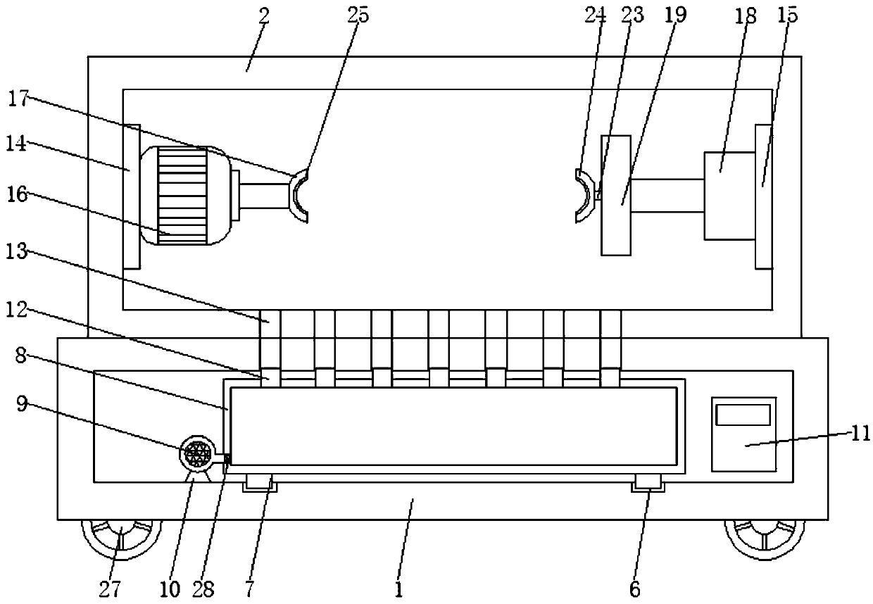
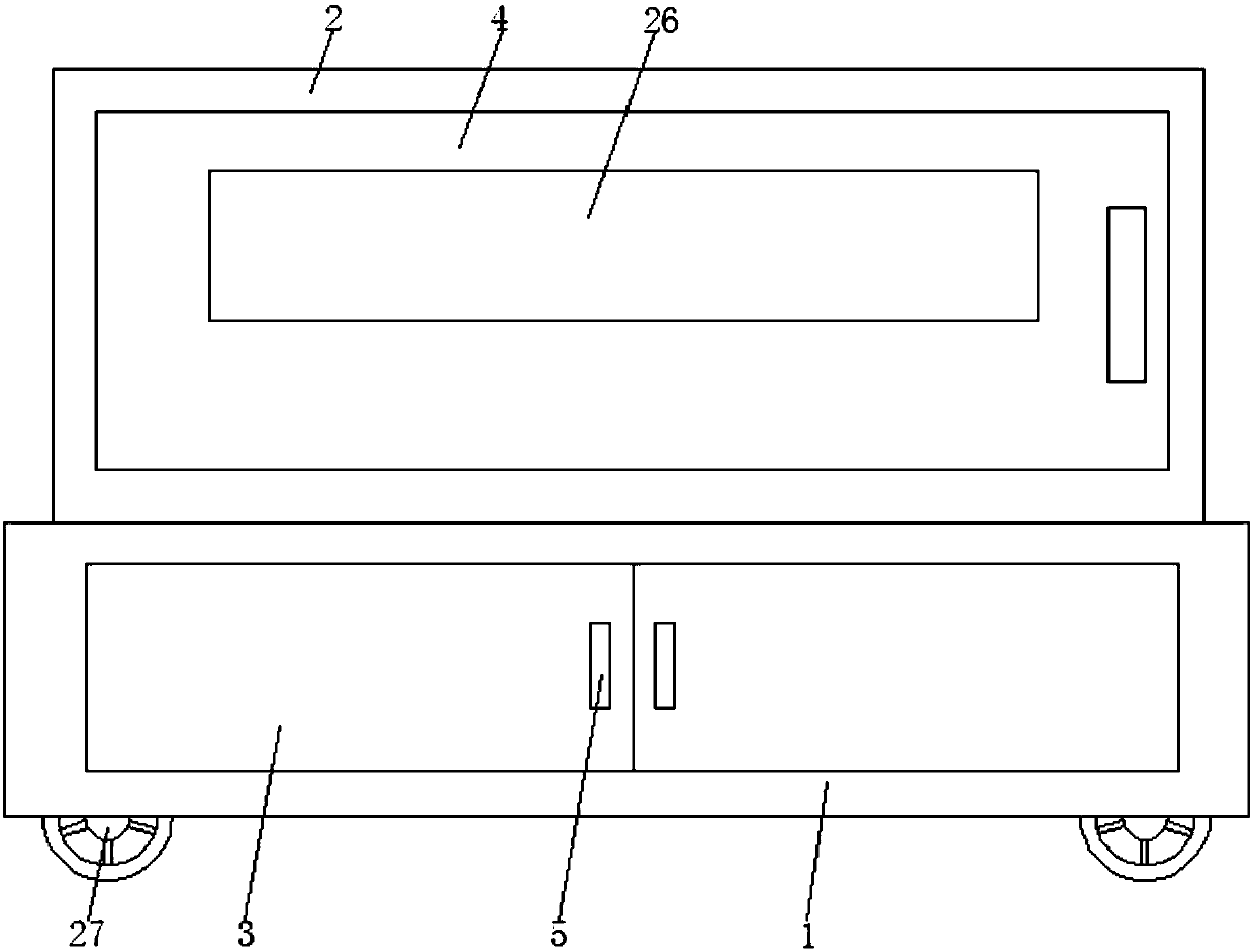
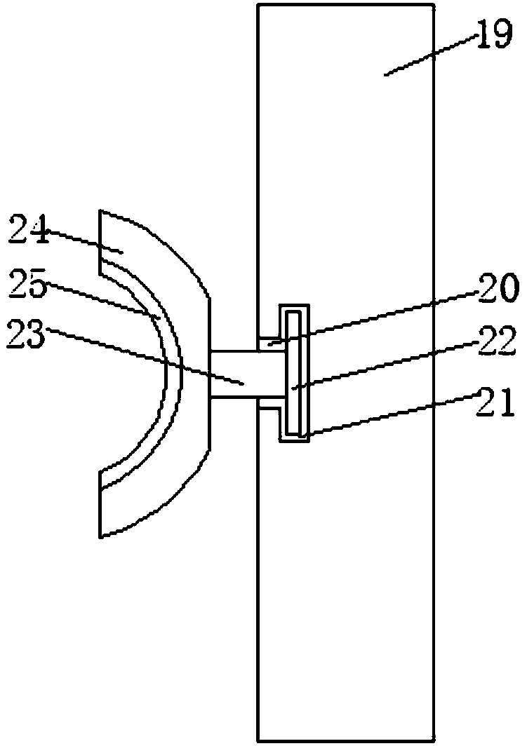

Image

  • Garbage collecting method for valve cleaning and clamping device
  • Garbage collecting method for valve cleaning and clamping device
  • Garbage collecting method for valve cleaning and clamping device

Examples


Embodiment Construction

[0025] The following will clearly and completely describe the technical solutions in the embodiments of the present invention with reference to the accompanying drawings in the embodiments of the present invention. Obviously, the described embodiments are only some, not all, embodiments of the present invention. Based on the embodiments of the present invention, all other embodiments obtained by persons of ordinary skill in the art without making creative efforts belong to the protection scope of the present invention.

[0026] see Figure 1-3 , a method for collecting garbage for a valve cleaning clamping device, comprising a collection box (1) and a cleaning box (2), the four corners of the lower surface of the collection box (1) are equipped with universal wheels (27), and the cleaning box (2) Fixedly connected on the upper surface of the collection box (1), the front of the collection box (1) is equipped with a first box door (3), the front of the cleaning box (2) is equip...


PUM


Abstract

The invention relates to the technical field of valve machining equipment, and discloses a garbage collecting method for a valve cleaning and clamping device. A collecting box, a through hole, a connecting hole and an exhaust fan are provided; the exhaust fan is started; waste chips in the cleaning box are absorbed into the collecting box through the through hole and the connecting pipe to achievethe effect of cleaning the waste chips and garbage, so that the influence on the equipment operation due to excessive waste chips is prevented, the cleanness of a worktable is kept, and the use is convenient; rubber layers are provided for increasing friction of a first clamping plate and a second clamping plate to enhance the clamping effect; and through arrangement of an observation window, theobservation of conditions in the cleaning box is more convenient, and meanwhile, the danger to persons caused by directly facing the cleaning work is prevented.

Description

technical field [0001] The invention relates to the technical field of valve processing equipment, in particular to a garbage collection method for a valve cleaning and clamping device. Background technique [0002] Valves are the control components in the fluid delivery system. They have the functions of cut-off, adjustment, flow diversion, reverse flow prevention, pressure stabilization, flow diversion and overflow pressure relief. Valves used in fluid control systems range from the simplest cut-off valve to extremely complex ones. There are various types and specifications of valves used in the automatic control system. Valves can be used to control the flow of various types of fluids such as air, water, steam, various corrosive media, mud, oil, liquid metal and radioactive media. Valves are also divided into cast iron valves, cast steel valves, stainless steel valves, chrome-molybdenum steel valves, chrome-molybdenum-vanadium steel valves, dual-phase steel valves, plast...

Claims


Application Information

Patent Timeline
Patent Type & Authority Applications(China)
IPC IPC(8): B08B5/04B23Q11/00
CPCB08B5/04B23Q11/0046
Inventor 陈可艳
Owner 陈可艳
Learn More