Electromagnetic shielding waveguide ventilation window

A technology of electromagnetic shielding and ventilation windows, which is applied in the directions of magnetic/electric field shielding, ventilation layout, electrical components, etc., can solve the problems of low strength and poor high temperature resistance, and achieve strong high temperature resistance, good damage resistance, and good overall The effect of sex and firmness

Active Publication Date: 2020-04-07
陕西智拓固相增材制造技术有限公司
View PDF6 Cites 0 Cited by
  • Summary
  • Abstract
  • Description
  • Claims
  • Application Information

AI Technical Summary

Problems solved by technology

[0004] The purpose of the present invention is to provide an electromagnetic shielding waveguide ventilation window to improve the problems of poor high temperature resistance and low strength of the electromagnetic shielding waveguide ventilation window
[0005] The purpose of the present invention is to provide a processing method of electromagnetic shielding waveguide ventilation window to improve the problems of poor high temperature resistance and low strength of electromagnetic shielding waveguide ventilation window

Method used


Image

  • Electromagnetic shielding waveguide ventilation window
  • Electromagnetic shielding waveguide ventilation window
  • Electromagnetic shielding waveguide ventilation window

Examples


Embodiment 1

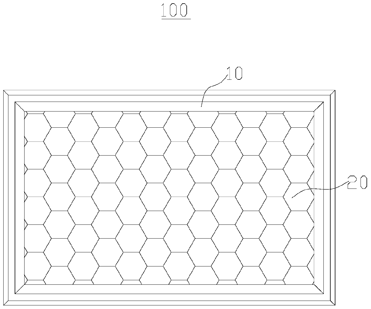
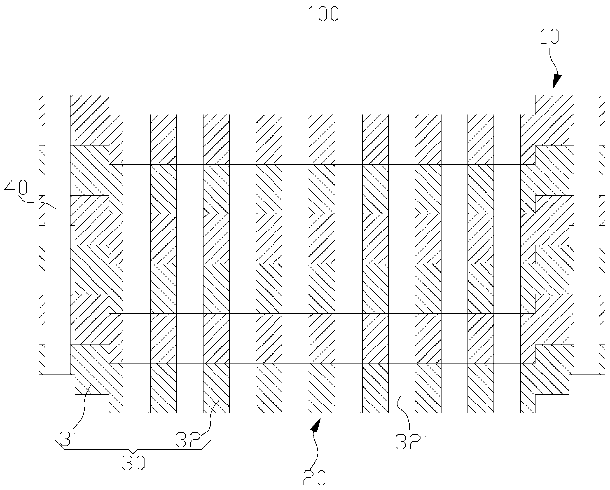
[0040] Such as image 3 As shown, the present embodiment provides an electromagnetic shielding waveguide ventilation window 100, including a limiting member 40 and a plurality of layers 30, all the layers 30 are sequentially arranged and connected from the bottom to the top, and the layers 30 and the layers 30 pass through the limiter. The position piece 40 is positioned.

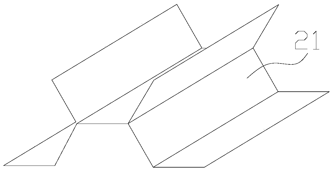
[0041] The layer 30 is made of metal, such as aluminum alloy, copper alloy, titanium alloy, stainless steel, high temperature alloy, high temperature tungsten, high temperature niobium, high temperature molybdenum and other metals. In this example, if Figure 4 As shown, the ply 30 is a circular structure. The ply 30 includes a bearing part 31 and a honeycomb part 32 located at the center of the bearing. The bearing part 31 and the honeycomb part 32 are of an integrated structure. It is a honeycomb structure, and the honeycomb portion 32 is provided with a plurality of honeycomb holes 321 , and the honeyc...

Embodiment 2

[0054] This implementation provides a processing method for the electromagnetic shielding waveguide ventilation window 100 in the above-mentioned embodiment, and the specific steps are as follows:

[0055] Machining of the ply 30: Firstly, the shape of each ply 30 is processed, so that the concave portion 34 and the protruding portion 33 are formed on the ply 30 . Next, hole machining is performed on each layer 30 so that a plurality of honeycomb holes 321 are formed at the center of the layer 30 and a limiting hole 314 is formed on the top of the layer 30 . The area of ​​the layer sheet 30 where the honeycomb holes 321 are located is the honeycomb portion 32 , and the area of ​​the layer sheet 30 other than the honeycomb portion 32 is the bearing portion 31 . The methods of shape processing and hole processing include but are not limited to mechanical processing, precision stamping, electrolytic etching, and chemical etching; after hole processing is performed on the layer 30...


PUM


Abstract

The invention provides an electromagnetic shielding waveguide ventilation window, which belongs to the technical field of anti-electromagnetic interference. The electromagnetically shielded waveguide louvers include a plurality of plies. The laminate includes a bearing part and a honeycomb part arranged at the center of the bearing part, and a plurality of honeycomb holes are arranged on the honeycomb part. All layers are arranged sequentially from bottom to top, all bearing parts are stacked to form an edge frame, and all honeycomb parts are stacked to form a central honeycomb body. After all the layers are stacked and connected, the load-bearing parts of all the layers form the edge frame, and the honeycomb parts of all the layers form the central honeycomb body. The central honeycomb body has good structural stability, is not easy to be damaged, and has strong high temperature resistance.

Description

technical field [0001] The invention relates to the technical field of anti-electromagnetic interference, in particular to an electromagnetic shielding waveguide ventilation window. Background technique [0002] The electromagnetic shielding waveguide ventilation window is a multi-functional product that meets the overall requirements of electromagnetic shielding, ventilation and mechanical properties. It has been widely used in various electronic equipment that requires high-efficiency electromagnetic shielding. Contradictory problems, that is, solve the electromagnetic shielding problem and solve the heat dissipation problem. [0003] The structure of the existing electromagnetic shielding waveguide ventilation window is composed of two parts, that is, a central honeycomb body and an edge outer frame, and the central honeycomb body and the edge outer frame are connected by a mechanical connection. The central honeycomb body is made of multiple corrugated thin plates by bo...

Claims


Application Information

Patent Timeline
Patent Type & Authority Patents(China)
IPC IPC(8): H05K9/00
CPCE06B5/10E06B7/02
Inventor 孙福张昊邵长斌王蒙蒙王莉敏许华辉李鹏飞
Owner 陕西智拓固相增材制造技术有限公司
Why Eureka
Try Eureka