
Construction system for subway station

Active Publication Date: 2015-07-30
GUANGZHOU JISHI CONSTR GRP +1
View PDF30 Cites 36 Cited by
  • Summary
  • Abstract
  • Description
  • Claims
  • Application Information

AI Technical Summary

Benefits of technology

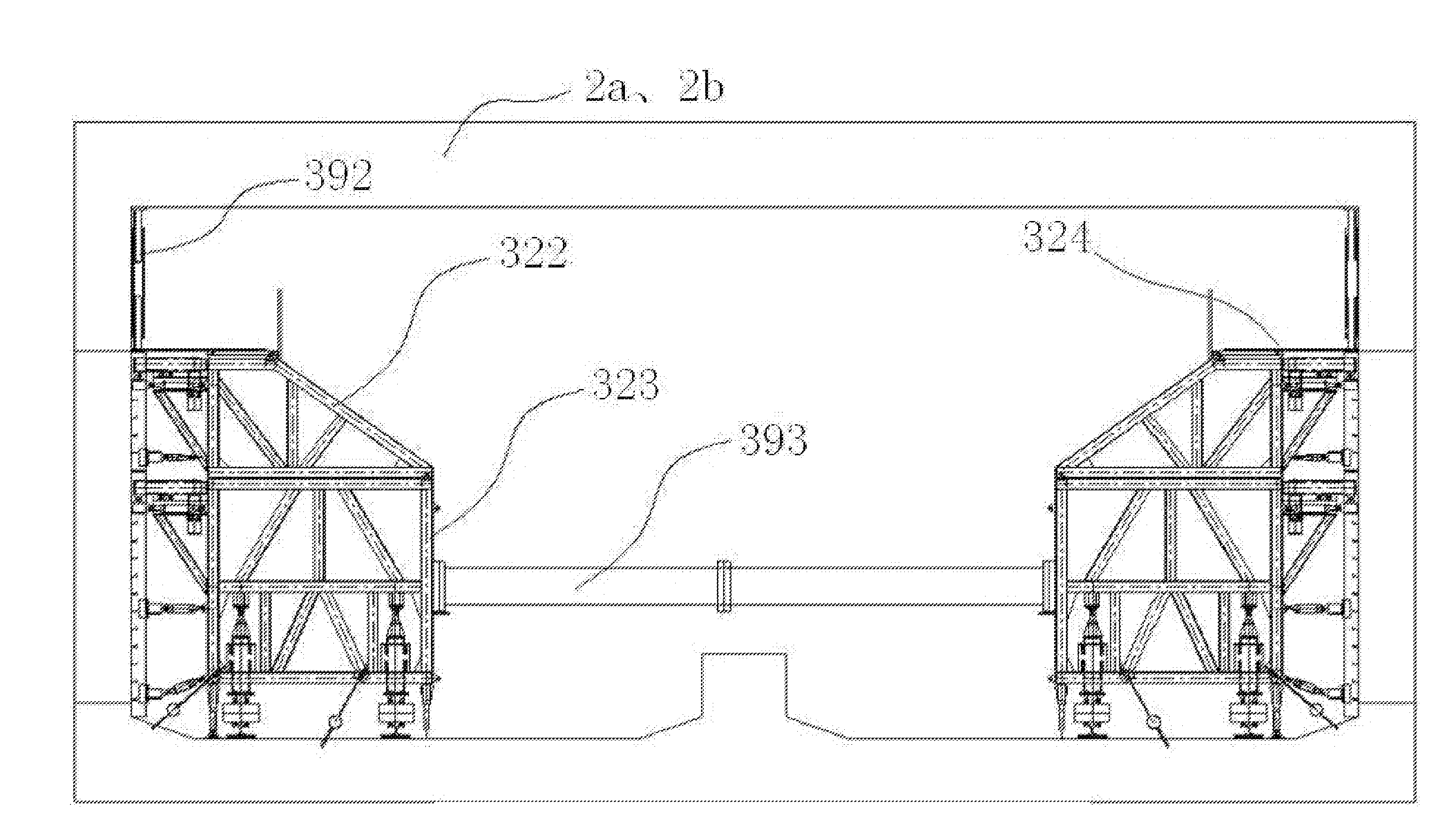
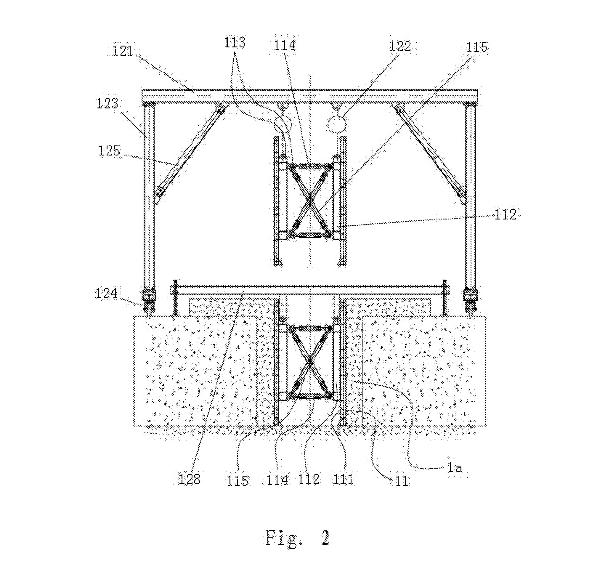
The present invention provides a construction system for a subway station that simplifies construction procedures, improves construction efficiency, reduces labor cost, and saves materials. The system includes a guide wall steel formwork system, a support beam steel formwork system, a sidewall trolley system, and a floor slab trolley system. These systems allow for precise positioning, fast adjusting, and stable structure, resulting in improved quality and safety. The floor slab trolley system can adapt to different floor slab widths and heights, and the system is suitable for large-area floor slabs. The use of tracks and trolleys instead of brackets and jackings further reduces labor and materials usage.

Problems solved by technology

Currently, in construction of concrete structures of a subway station, it is most often to employ a construction method using wood formwork combined with respective bracket system, which leads to drawbacks such as few formwork cycle times, high cost, huge labor amount, long construction duration, etc.
(1) In a conventional construction process of guide walls for underground continuous walls, mounting is usually performed using a wood formwork, the overall rigidity of which is reinforced by using steel pipes, square timber, shaped steel and the like as back ribs, and then a rod member is used as a support so as to fix the formwork in place. The problem is that, since the components are all separated, every single component needs to be assembled and disassembled for each use, and is then moved manually to a next working site for a next cycle operation. Some of the continuous walls have great lengths, for example up to 1000 meters, and the construction duration is short. In such cases, if a wood formwork is used according to conventional processes, a large amount of material is to be used, and a labor-intensive and time-consuming assembling and disassembling is to be performed. Moreover, a common formwork is usually small, and therefore high accuracy is required in mounting and calibrating.
(2) In a conventional formwork for concrete support beam, mounting is usually performed using artificial wood formwork alone or combination of steel formwork and counter rod. When a wood formwork is used for mounting, since expansion joints of a wood formwork are big, slurry leakage is likely to occur, flatness of the concrete is difficult to achieve, stability of the support system is poor, the concrete quality is hard to control, and the formwork cannot be dissembled in advance and is used in a large number. When small steel formworks are used for mounting, since a plurality of them are pieced together, the seamings are difficult to treat, thereby increasing labor intensity. In a conventional formwork process, it is required to pre-burry plastic tubes of counter rod in the steel bar reinforced concrete in large numbers. The procedure is complicated, and usually leads to spatial interference between counter rods and the steel bars in the concrete, poor reliability, and high aspect ratio. In such cases, the formwork itself tends to twist, does not have sufficient strength to be a strong support, and is subject to lateral torsion when bearing high pressure after the concrete is cast. In the case of an excessive deformation, the requirement of a support beam cannot be met, and even crack and slurry leakage could occur at the connecting point and thus inclined supports need to be provided at two sides of the support beam formwork.
(3) In the concrete construction of conventional station sidewalls and floor slabs, full-framing method is used combined with wood formwork. In this process, it is needed to build a steel-pipe bracket in the foundation pit with a same width, and piece the wood formwork together piece by piece. The piecing of the steel-pipe bracket requires huge amount of labor and takes a long period of time. In the mounting of a wood formwork, operation space is limited, working environment is bad and piecing of the formwork is slow. Construction quality of the formwork and steel-pipe bracket could hardly be ensured and reliability is low. When the concrete is cast, deformation of sidewalls and slurry leakage of the concrete are likely to occur. It takes multiple operations to piece the wood formwork together, resulting in poor flatness of the concrete surface and possible height difference across the seaming. As for the components for cycle use, such as wood formwork and its bracket, the disassembly process is time consuming, the cycle period is long, and the components are often used in a large quantity. Furthermore, high skill and intensive labor and thus a large number of workers is required, with the disadvantages of low efficiency and high labor cost.

Method used


Image

  • Construction system for subway station
  • Construction system for subway station
  • Construction system for subway station

Examples


Embodiment Construction

[0041]The technical solutions of the embodiments of the present invention are described clearly and completely in the following, in conjunction with the drawings of the embodiments, the embodiments described being only some but not all of the embodiments of the present invention. Based on the embodiments described in the present invention, one skilled in the art can make other embodiments without an inventive step, all falling within the protection scope of the present invention.

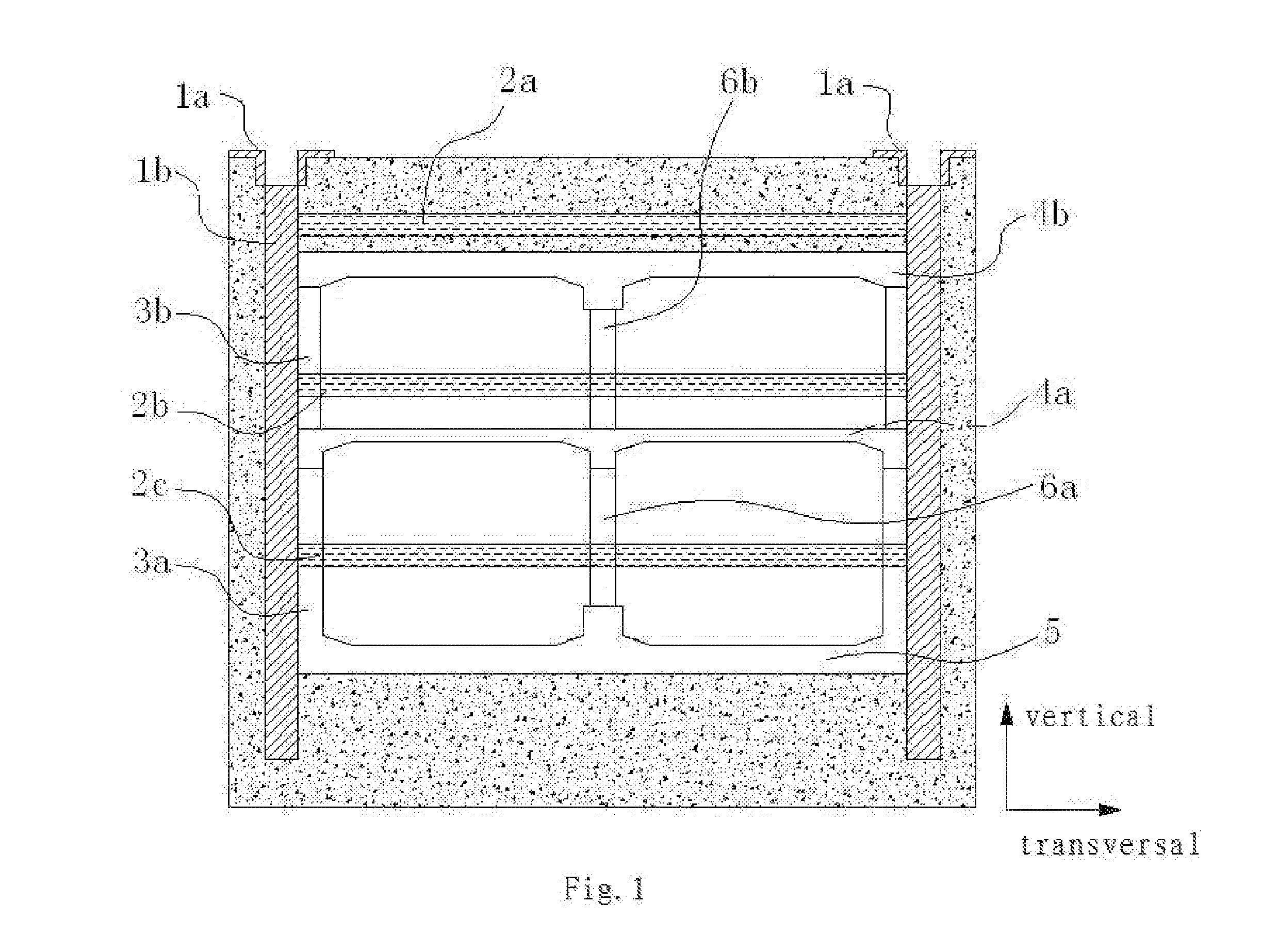
[0042]What is shown in FIG. 1 is an embodiment of a construction system for a subway station, wherein the total length of the subway station is constructed to be 381.2 m, the width of the station envelope in a standard section 19 m, and the total building area 15224 m2. A two-storey and two-span frame structure of an all-cut type is used, wherein the underground first storey is the storey of station hall and the underground second storey is the storey of station platform. In the embodiments, the construction...


PUM


Abstract

Described herein is a construction system for a subway station, wherein the construction of guide walls is accomplished using a guide wall steel formwork system, the construction of support beams is accomplished using a support beam steel formwork system, the construction of sidewalls is accomplished using a sidewall trolley, and the construction of floor slabs is accomplished using a floor slab trolley.

Description

CROSS-REFERENCE TO PRIOR APPLICATION[0001]The present application claims the priority of Chinese Patent Application No. 201410042907.4 filed on Jan. 29, 2014, the entirety of which is incorporated herein by reference.FIELD OF THE INVENTION[0002]The present application relates to a construction system for a subway station, particularly to construction of guide walls for underground continuous walls, construction of concrete support beam of foundation pit, construction of subway station sidewalls, and construction of subway station floor slabs.BACKGROUND OF THE INVENTION[0003]Currently, in construction of concrete structures of a subway station, it is most often to employ a construction method using wood formwork combined with respective bracket system, which leads to drawbacks such as few formwork cycle times, high cost, huge labor amount, long construction duration, etc. Specifically, the drawbacks are as follows:[0004](1) In a conventional construction process of guide walls for un...

Claims


Application Information

Patent Timeline
IPC IPC(8): E02D29/00E21D11/00E21D11/10E21D13/00
CPCE02D29/04E21D11/10E21D11/003E21D13/00
Inventor DING, CHANGYINHE, BINGQUANKE, DEHUICHEN, MUZHENMO, JINHUANG, PINGYUJIANG, MINGXITANG, WEICAILI, WENXIANLI, YUQILEI, XIONGWUQIU, JIANTAOQIN, JIANXINLI, WENLONGQIU, SHILIANGHE, DENGJIA
Owner GUANGZHOU JISHI CONSTR GRP
Learn More