Packaging body and manufacturing method thereof
A manufacturing method and package technology, applied in semiconductor/solid-state device manufacturing, electric solid-state devices, semiconductor devices, etc., can solve problems such as shedding, product failure, and difficulty in using implantable device surface protection, and achieve high fatigue resistance , Improve the effect of adhesion
- Summary
- Abstract
- Description
- Claims
- Application Information
AI Technical Summary
Problems solved by technology
Method used
Image
Examples
no. 1 approach
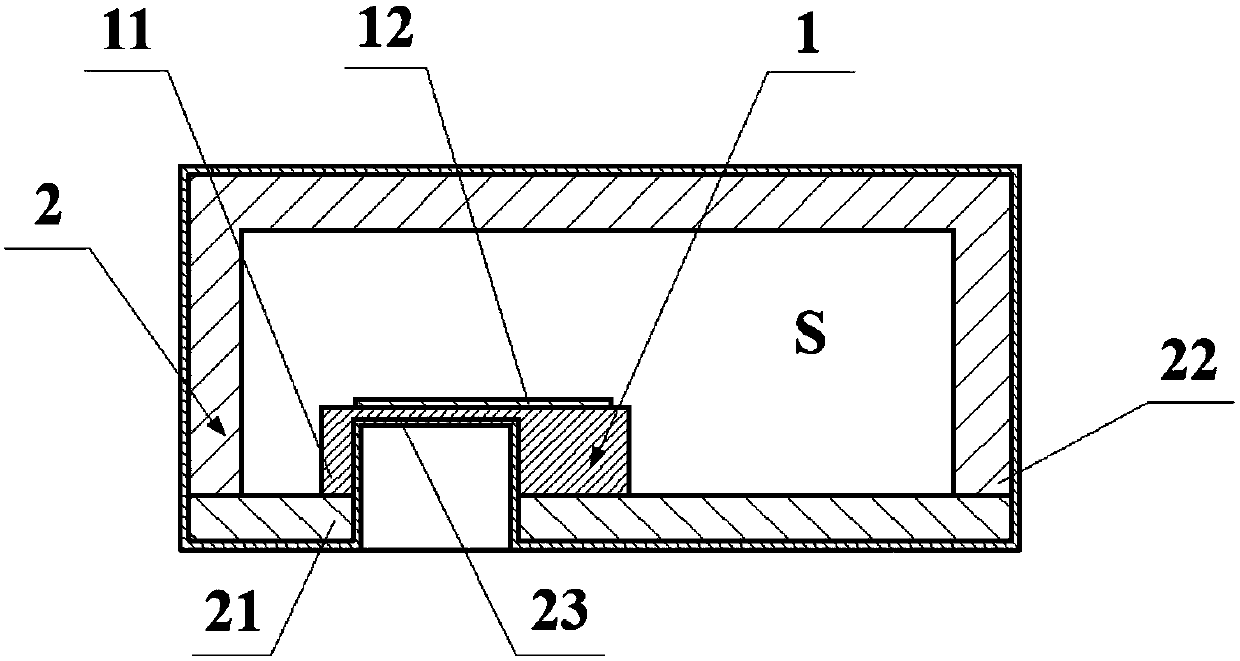
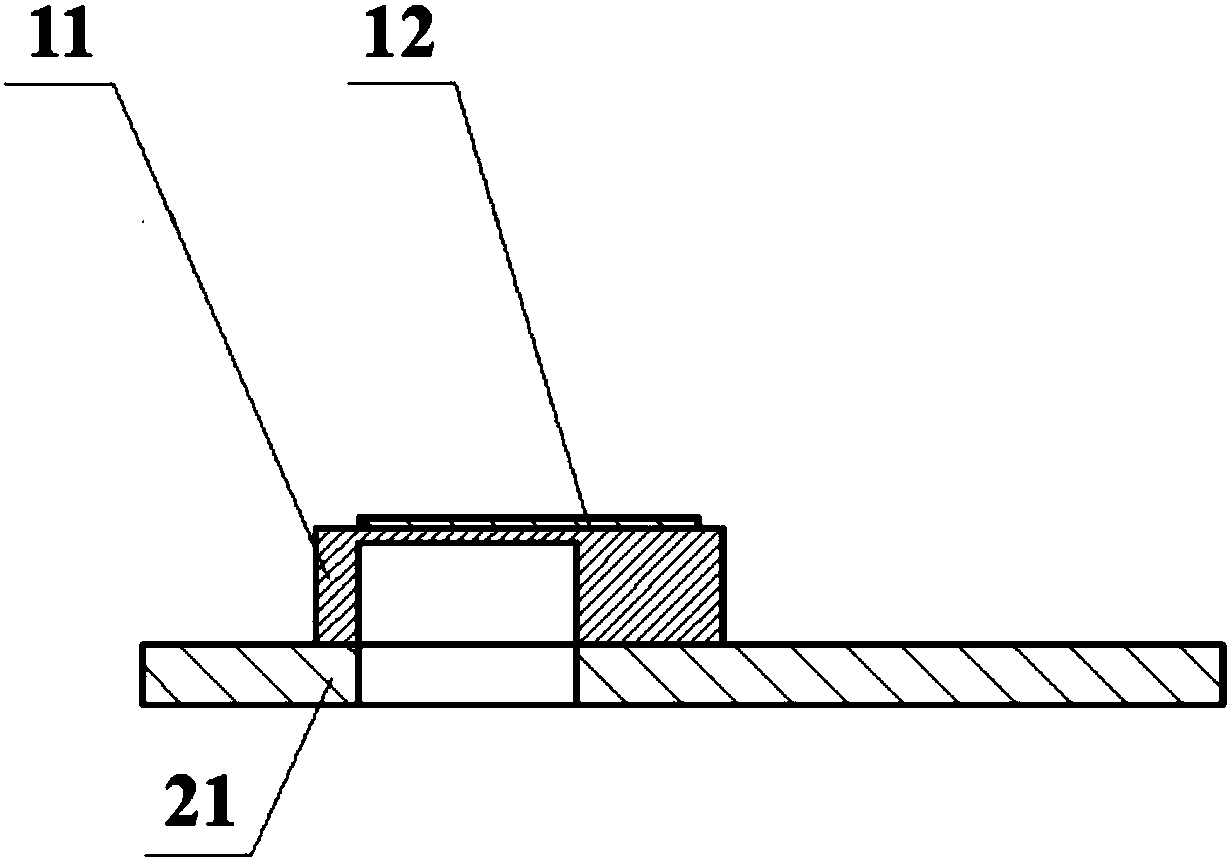
[0036] Figure 1a to Figure 1d An implantable package according to a first embodiment of the present invention is shown comprising an implantable device 1 and a packaging structure 2 for the implantable device 1 .
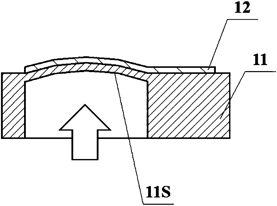
[0037] In this embodiment, as Figure 1a to Figure 1d As shown, the implantable device 1 includes a pressure sensor that senses pressure with the concave surface 11S of the silicon cup. In this embodiment, the movable part is also a sensing part), and other parts of the pressure sensor other than the pressure sensing part are immovable parts (non-sensing parts). like Figure 1b As shown, when pressure acts on the silicon cup concave surface (predetermined surface) 11S of the pressure-sensing portion of the pressure sensor, the silicon cup concave surface 11S is deformed, so that the pressure sensor measures the pressure (predetermined parameter) through the deformation of the silicon cup concave surface 11S. ).
[0038] In this embodiment, the encapsulation struc...
no. 2 approach
[0047] like Figure 2a to Figure 2c As shown, the basic structure of the package body 1 according to the second embodiment of the present invention is substantially the same as that of the package body 1 according to the first embodiment of the present invention, and the difference between the two is that the implantable device 1 has a The structure is different.
[0048] Specifically, in this embodiment, the implantable device 1 includes, in addition to the above-mentioned pressure sensor, a signal processing module 14 and a wireless power supply and wireless transmission module 15 connected to the pressure sensor through a lead 13 , and the signal processing module 14 and the wireless power supply and wireless transmission module 15 are all accommodated in the accommodation cavity S of the package structure 2 as the immovable part and the non-sensing part of the implantable device 1 . Since the package components are made of materials such as ceramics or glass, electrostati...
no. 3 approach
[0050] like Figure 3a to Figure 3e As shown, the basic structure of the package body 1 according to the third embodiment of the present invention is substantially the same as the basic structure of the package body 1 according to the second embodiment of the present invention, the difference between the two is that the package structure 2 also includes a flexible The polymer encapsulates the protective layer 24, the base 21 is formed with the guide tube 211 and the structure of the pressure sensor is different.
[0051] Specifically, in this embodiment, after the implantable device 1 is encapsulated by the encapsulation structure 2 , the outer side of the cover plate 22 is further covered with a flexible polymer encapsulation protection layer 24 such as silicone rubber, the flexible polymer encapsulation protection The layer 24 is located on the outside of the encapsulation coating 23 to improve the mechanical compatibility of the entire implantable package 1 .
[0052] Furthe...
PUM
| Property | Measurement | Unit |
|---|---|---|
| Thickness | aaaaa | aaaaa |
Abstract
Description
Claims
Application Information
 - R&D
- Intellectual Property
- Life Sciences
- Materials
- Tech Scout
- Unparalleled Data Quality
- Higher Quality Content
- 60% Fewer Hallucinations
Browse by: Latest US Patents, China's latest patents, Technical Efficacy Thesaurus, Application Domain, Technology Topic, Popular Technical Reports.
© 2025 PatSnap. All rights reserved.Legal|Privacy policy|Modern Slavery Act Transparency Statement|Sitemap|About US| Contact US: help@patsnap.com


