Electric pressure cooker steam extraction device

A technology of electric pressure cooker and discharge device, which is applied to the structure of utensils with integral electric heating devices, garbage cans, cooking utensils, etc., and can solve the problem of large solenoid valve 230 itself, large space for solenoid valve 230, and large solenoid valve power, etc. problems, to achieve the effect of simplifying the structure, reducing production costs and reducing accessories

Pending Publication Date: 2018-03-23
宁波华宝食为天电器科技有限公司
View PDF5 Cites 65 Cited by
  • Summary
  • Abstract
  • Description
  • Claims
  • Application Information

AI Technical Summary

Problems solved by technology

However, in order to adjust the internal pressure of the inner tank 120 in the operation process of this conventional electric pressure cooker, the pressure relief valve 220 can only be opened and closed manually. Moreover, the installation of the electromagnetic valve 230 itself will be very large, and the space required for the installation of the electromagnetic valve 230 will be large, which will at least bring about the most intuitive problem of cost increase.

Method used


Image

  • Electric pressure cooker steam extraction device
  • Electric pressure cooker steam extraction device
  • Electric pressure cooker steam extraction device

Examples


Embodiment 1

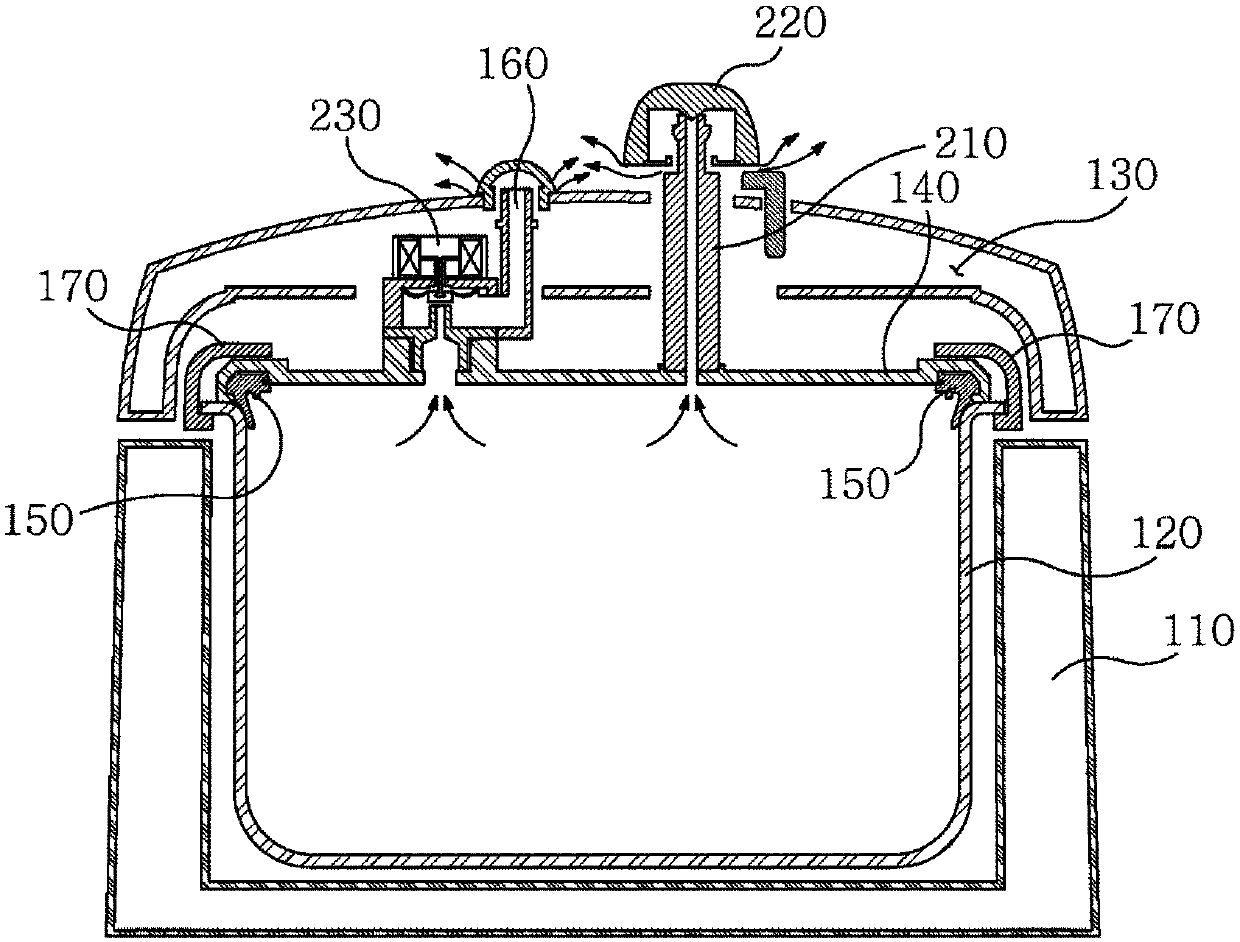
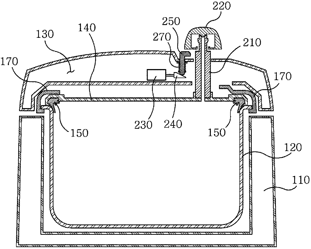
[0027] Such as figure 2 As shown, the steam circulation pipe 210 passes through the inner pot cover 140 and the outer cover 130 of the electric pressure cooker, thereby communicating the inside of the pressure cooker with the outside air, and serves as the steam passage pipe 210 .

[0028] The pressure relief valve 220 is arranged on the upper half of the steam circulation pipe 210, and moves up and down within a certain distance in the upper half of the steam circulation pipe 210. With the operation of the pressure relief valve 220, the steam outlet 180 is opened, Internal steam escapes from this, thereby regulating the internal pressure of the pressure cooker.

[0029] The solenoid valve 230 is arranged inside the outer cover 130, and the solenoid valve is provided with a plunger 240. The plunger 240 and the solenoid valve 230 operate in linkage. The end of the plunger 240 is provided with a "<" or a "<" wedge-shaped inclined end.

[0030] The lifting pin 250 and the elec...

Embodiment 2

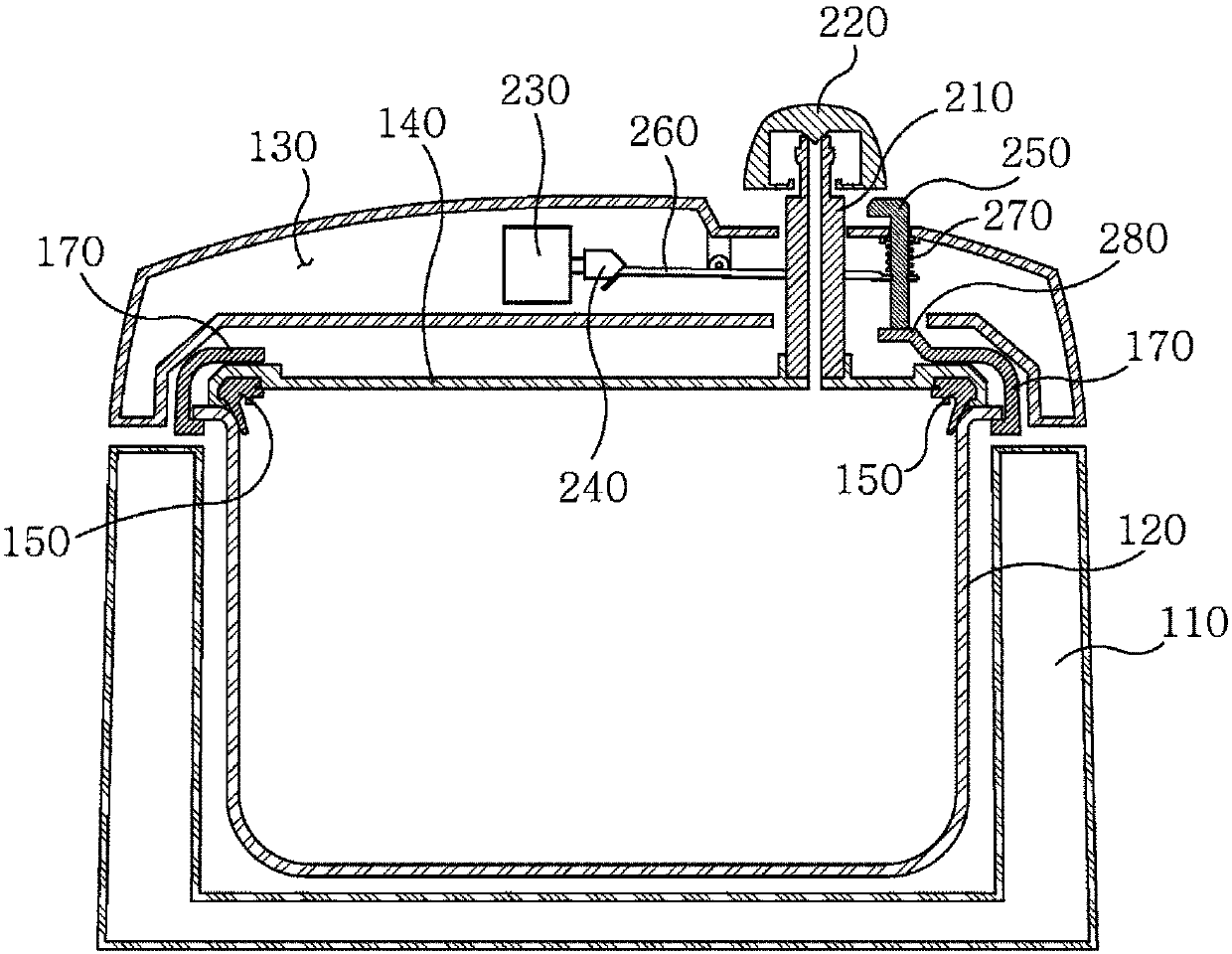
[0034] Such as image 3 The figure shows another implementation example of the present invention, which adopts a structure in which the action transmission rod 260 is embedded between the plunger 240 and the lifting pin 250, wherein the steam circulation pipe 210, the pressure relief valve 220, the solenoid valve 230, the plunger 240, etc. Structure and function are identical with embodiment 1. The plunger 240 is not connected to the lift pin 250 , and when the plunger 240 rotates the transmission rod 260 , the lift pin 250 is linked to lift.

[0035] The action transmission rod 260 is connected by a pin and is arranged inside the outer cover 130 . The partial end of the action transmission rod 260 is connected with the inclined end of the plunger 240 , and the action transmission rod 260 rotates up and down with the operation of the plunger 240 . That is, when the plunger 240 advances (moves to the right), the motion transmitting lever 260 rotates counterclockwise, and when ...


PUM


Abstract

The invention discloses an electric pressure cooker steam extraction device comprising a steam runner pipe, a pressure release valve, a solenoid valve and an elevating pin. The steam runner pipe passes through a pot cover on the inner side of the pressure cooker and an external cover, so the interior of the pressure cooker can communicate with exterior; the pressure release valve is arranged on the upper half part of the steam runner pipe and moves up and down in a certain distance range to the upper half part of the steam runner pipe, so a steam extracting port can be controlled and pressureof the interior of the pressure cooker can be adjusted; the elevating pin is arranged under the pressure release valve and linked with the solenoid valve on the inner side of the external cover to move up and down; and when the elevating pin rises and protrudes out of the external side of the external cover, the pressure release valve can be lifted and the steam runner pipe is opened. The invention provides an electric pressure cooker capable of automatically adjusting interior pressure minimizes fittings and reduce production cost.

Description

technical field [0001] The invention relates to the field of steam discharge devices, more specifically, it relates to a steam discharge device for an electric pressure cooker. Background technique [0002] According to the principle that the boiling point of the electric pressure cooker rises with the increase of the internal pressure, cooking is carried out while maintaining the internal pressure of the pressure cooker. During the cooking process, there is a pressure relief valve to adjust the internal pressure of the pressure cooker and the internal steam is discharged after the cooking is completed. The steam outlet is the setting point. [0003] Such as figure 1 Shown is the conventional electric pressure cooker section structure. Its electric pressure cooker includes a body 110 , an inner container 120 and an outer cover 130 . The inner container 120 is provided inside the main body 110 , and the upper part of the main body 110 is provided with an openable outer cove...

Claims


Application Information

Patent Timeline
Patent Type & Authority Applications(China)
IPC IPC(8): A47J27/086A47J36/38
CPCA47J27/086A47J36/38A47J27/002A47J27/004A47J27/0802A47J27/092Y10S220/912
Inventor 金永钟王军川李开琴
Owner 宁波华宝食为天电器科技有限公司
Why Eureka
Try Eureka