Plank cutting device

A technology for cutting devices and boards, which is applied in the direction of feeding devices, clamping devices, sawing components, etc., and can solve the problems of slow cutting speed, time-consuming and labor-intensive problems

Inactive Publication Date: 2018-03-23
钟清
View PDF10 Cites 17 Cited by
  • Summary
  • Abstract
  • Description
  • Claims
  • Application Information

AI Technical Summary

Problems solved by technology

[0005] In order to overcome the disadvantages of manual cutting of wooden boards, such as time-consuming and labor-intensive, slow cutting speed, and a large amount of sawdust easily appearing in the cutting process, which affects the surrounding environment, the technical problem to be solved by the present invention is to provide a time-saving, labor-saving, cutting speed Fast, wood cutting device that can collect and dispose of sawdust in the cutting process without affecting the surrounding environment

Method used


Image

  • Plank cutting device
  • Plank cutting device
  • Plank cutting device

Examples


Embodiment 1

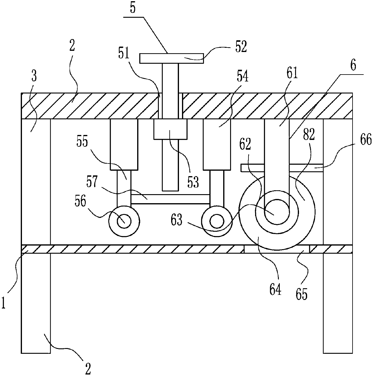
[0035] A wood cutting device such as Figure 1-5 As shown, it includes a placement board 1, legs 2, poles 3, a top board 4, a pressing device 5 and a cutting device 6, and the left and right sides of the bottom of the placement board 1 are symmetrically equipped with outriggers 2, and the top of the placement board 1 is left and right. Both sides are symmetrically equipped with struts 3, and a top plate 4 is installed between the tops of the struts 3 on the left and right sides. The left side of the top plate 4 is provided with a pressing device 5, and the pressing part of the pressing device 5 is located above the placement plate 1. A cutting device 6 is provided on the right side of the bottom of the top plate 4 .

Embodiment 2

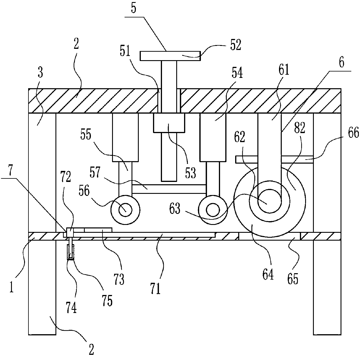
[0037] A wood cutting device such as Figure 1-5 As shown, it includes a placement board 1, legs 2, poles 3, a top board 4, a pressing device 5 and a cutting device 6, and the left and right sides of the bottom of the placement board 1 are symmetrically equipped with outriggers 2, and the top of the placement board 1 is left and right. Both sides are symmetrically equipped with struts 3, and a top plate 4 is installed between the tops of the struts 3 on the left and right sides. The left side of the top plate 4 is provided with a pressing device 5, and the pressing part of the pressing device 5 is located above the placement plate 1. A cutting device 6 is provided on the right side of the bottom of the top plate 4 .

[0038] Pressing device 5 comprises screw rod 52, nut 53, sleeve 54, movable bar 55, roller 56 and connecting plate 57, and top plate 4 left side has threaded hole 51, is provided with screw rod 52 in threaded hole 51, is provided with on the bolt. Nut 53, the to...

Embodiment 3

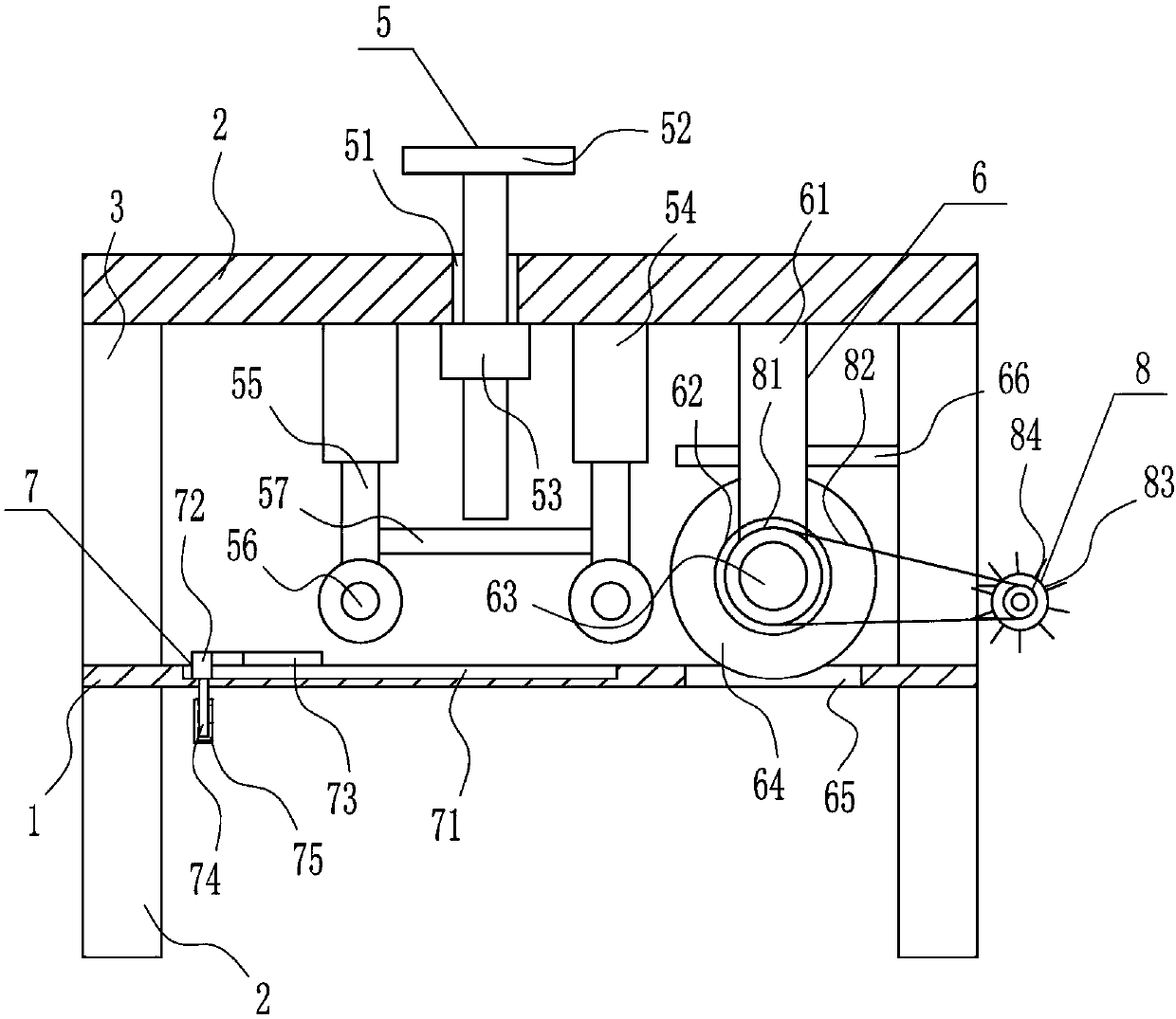
[0040] A wood cutting device such as Figure 1-5 As shown, it includes a placement board 1, legs 2, poles 3, a top board 4, a pressing device 5 and a cutting device 6, and the left and right sides of the bottom of the placement board 1 are symmetrically equipped with outriggers 2, and the top of the placement board 1 is left and right. Both sides are symmetrically equipped with struts 3, and a top plate 4 is installed between the tops of the struts 3 on the left and right sides. The left side of the top plate 4 is provided with a pressing device 5, and the pressing part of the pressing device 5 is located above the placement plate 1. A cutting device 6 is provided on the right side of the bottom of the top plate 4 .

[0041] Pressing device 5 comprises screw rod 52, nut 53, sleeve 54, movable bar 55, roller 56 and connecting plate 57, and top plate 4 left side has threaded hole 51, is provided with screw rod 52 in threaded hole 51, is provided with on the bolt. Nut 53, the to...


PUM


Abstract

The invention particularly relates to a plank cutting device. The plank cutting device can save time and labor, is high in cutting speed, can collect wood bits generated in the cutting process, and does not affect the surrounding environment. To achieve the above technical purposes, the plank cutting device comprises a placement board and the like; supporting legs are installed on the left side and the right side of the bottom of the placement board symmetrically; supporting rods are installed on the left side and the right side of the top of the placement board symmetrically; a top board is installed between the top ends of the supporting rods on the left side and the right side; a compressing device is arranged on the left side of the top board; a compressing component of the compressingdevice is located above the placement board; and a cutting device body is arranged on the right side of the bottom of the top board. Through a pushing device, the situation that a person makes contact with a plank and pushes the plank with hands is not needed, the person is not likely to be cut by a saw web, and a collection device can collect the wood bits generated in the cutting process, so that the effects of saving time and labor and being high in cutting speed are achieved.

Description

technical field [0001] The invention relates to a wood cutting device, in particular to a wood cutting device. Background technique [0002] Wood is the lignified tissue of plants capable of secondary growth, such as trees and shrubs. After the primary growth of these plants ends, the vascular cambium in the rhizome becomes active, developing bast outward and wood inward. [0003] When the wood board needs to be used, it needs to be cut to make the wood board better. However, when the wood board is cut manually, it is time-consuming and laborious, the cutting speed is slow, and a large amount of sawdust is easy to appear during the cutting process, which will affect the surrounding environment. Therefore, it is urgent It is necessary to develop a wood cutting device that saves time and labor, has a fast cutting speed, and can collect and process wood chips that appear during the cutting process without affecting the surrounding environment. Contents of the invention [0...

Claims


Application Information

Patent Timeline
Patent Type & Authority Applications(China)
IPC IPC(8): B27B5/06B27B5/22B27B29/02B27B25/10B27B27/04B27G3/00
CPCB27B5/06B27B5/22B27B25/10B27B27/04B27B29/02B27G3/00
Inventor 钟清李伟张晓春
Owner 钟清
Why Eureka
Try Eureka