Creel following system

A creel and ground rail technology, applied in the field of following systems, can solve the problems of high cost and poor driving force of the creel following system, and achieve the effects of avoiding friction and adhesion, reducing wear and short yarn paths.

Pending Publication Date: 2018-03-23
HARBIN COMPOSITE EQUIP
View PDF6 Cites 2 Cited by
  • Summary
  • Abstract
  • Description
  • Claims
  • Application Information

AI Technical Summary

Problems solved by technology

[0007] The purpose of the present invention is to solve the problems of high cost and poor driving force in the existing creel following system

Method used


Image

  • Creel following system
  • Creel following system
  • Creel following system

Examples


specific Embodiment approach 1

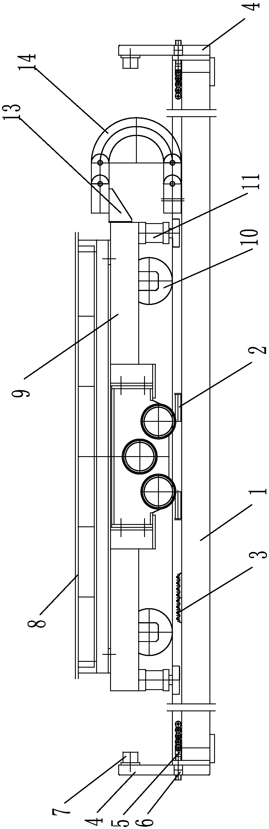
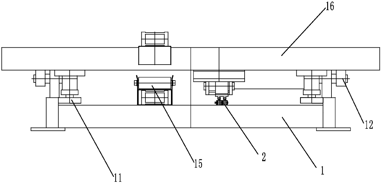
[0029] Specific implementation mode one: combine Figure 1 to Figure 3 Describe this embodiment, a creel following system of this embodiment, which includes a floor rail assembly, a traveling mechanism and a driving mechanism, the floor rail assembly is installed horizontally, the traveling mechanism directly rides on the floor rail assembly, and the driving mechanism is installed on the traveling mechanism , and the driving mechanism drives the traveling mechanism to move on the ground rail assembly, and the creel 8 is installed on the traveling mechanism.

specific Embodiment approach 2

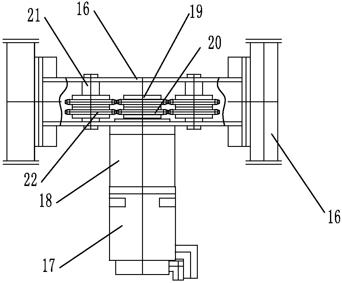
[0030] Specific implementation mode two: combination Figure 1 to Figure 3 Describe this embodiment, the ground rail assembly of this embodiment includes a ground rail 1 and a stationary chain 2, the ground rail 1 is laid horizontally, and the stationary chain 2 is installed on the upper end surface of the ground rail 1 along the length direction of the ground rail 1. In this way, the stationary chain 2 does not move on the ground rail 1 after it is installed on the ground rail 1. The driving mechanism is driven by the drive sprocket 20 to run on the ground rail 1, which is cheap and easy to implement. Other compositions and connections are the same as in the first embodiment.

specific Embodiment approach 3

[0031] Specific implementation mode three: combination figure 1 Referring to this embodiment, the floor rail assembly of this embodiment further includes a plurality of chain reinforcement bars 3 installed on the upper surface of the floor rail 1 , and the chain reinforcement bars 3 engage with the stationary chain 2 . Such arrangement can effectively ensure that the driving sprocket 20 in motion can mesh with the stationary chain 2 from time to time, preventing the derailment of the sprocket and making the operation safer and more reliable. A number of chain reinforcement bars effectively segment the entire length of the chain, shortening the effective length of the chain under load and increasing the transmission rigidity in a wide range. Other compositions and connections are the same as those in the second embodiment.


PUM


Abstract

The invention relates to a following system, in particular to a creel following system. The creel following system is used for solving the problems that an existing gear and rack transmission following system is high in cost and poor in drive force and a loop chain drive following system is low in movement precision, poor in rapid responsiveness and low in running speed. According to the creel following system, a ground track assembly is horizontally arranged, a walking mechanism is directly arranged on the ground track assembly in a striding manner, a drive mechanism is arranged on the walking mechanism, and a creel is arranged on the walking mechanism. Compared with gear and rack transmission with very high requirements for positioning and guiding, single-chain transmission adopts a three-wheel layout structure form, guide chain wheels on the two sides are in charge of guiding and axially positioning chains, the requirement of drive chain wheels for guiding and positioning is very low, and therefore the cost of single-chain transmission is far lower than that of gear and rack transmission. According to the three-wheel layout structure form, the number of teeth of the chain wheelsparticipating in driving is relatively large, and therefore the drive capability of single-chain transmission is far higher than that of gear and rack transmission. The creel following system is usedfor winding composite materials.

Description

technical field [0001] The invention relates to a following system, in particular to a creel following system. Background technique [0002] With the rapid development of science and technology, the technology of resin and glass fiber is constantly improving, and the application of composite winding products in various industries is becoming more and more extensive, and its products are developing in the direction of large size specifications (large diameter, super long length), In order to give full play to the performance of raw materials as much as possible, meet some special process requirements, and further improve production efficiency, the number of yarn clusters should be increased as much as possible during winding. The traditional fixed creel winding method can no longer meet such requirements. Therefore, in the winding The creel following system is introduced to keep the synchronization between the winding car and the creel car during the winding process, which so...

Claims


Application Information

Patent Timeline
Patent Type & Authority Applications(China)
IPC IPC(8): B65H54/72
CPCB65H54/72
Inventor 金永根温虓瑞刘阳陈宇宁逄博黄永亮陈钰
Owner HARBIN COMPOSITE EQUIP
Why Eureka
Try Eureka