House building rebar connecting structure

A technology for building steel bars and connecting structures, which is applied in the direction of building components, building structures, buildings, etc., can solve the problems of unstable connection between clips and telescopic bosses, difficult manufacturing and processing, and gaps in walls, so as to overcome the problems of connection Instability, save construction production cost, reduce the effect of operation intensity

Inactive Publication Date: 2018-03-23
CHENGDU LEYE TECH CO LTD
View PDF1 Cites 3 Cited by
  • Summary
  • Abstract
  • Description
  • Claims
  • Application Information

AI Technical Summary

Problems solved by technology

[0002] In the existing building structure, the grouting steel bar connection structure is mainly used. The steel bar connection is mainly connected and installed by bundling or sleeves. The bundling is wrapped with iron wire at the cross point of the steel bar. The disadvantage is that the iron wire is a product that is easy to corrode , after long-term thermal expansion and contraction and rain corrosion, it is easy to break, causing the steel bars to be disconnected from each other. The main disadvantages of the traditional sleeve connection are that it is difficult to manufacture and process, and the processing efficiency is low, and it is easy to leave gaps during the grouting process. Cause wall cracks, in the prior art, for example, the invention patent with application number 201621194413.9 includes ribbed steel bars, smooth round steel bars and connecting pipe fittings, the outer walls of the ribbed steel bars are equidistantly provided with transverse ribs, and the connecting The pipe fittings include clips, telescopic bosses, compression holes, clip welding joints, anti-slip ribs, bending openings, and gaps. The connecting pipe fittings are tubular structures, and the smoo

Method used


Image

  • House building rebar connecting structure
  • House building rebar connecting structure
  • House building rebar connecting structure

Examples


Example Embodiment

[0014] The technical solutions in the embodiments of the present invention will be clearly and completely described below in conjunction with the accompanying drawings in the embodiments of the present invention. Obviously, the described embodiments are only a part of the embodiments of the present invention, rather than all the embodiments. Based on the embodiments of the present invention, all other embodiments obtained by those of ordinary skill in the art without creative work shall fall within the protection scope of the present invention.
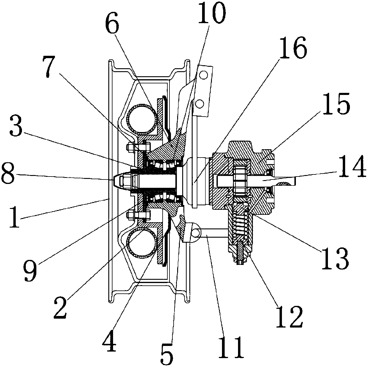
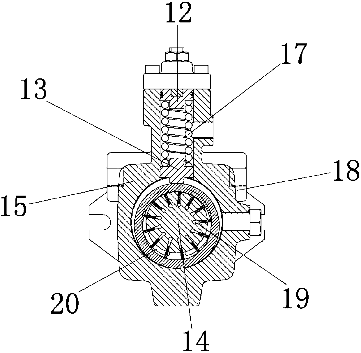
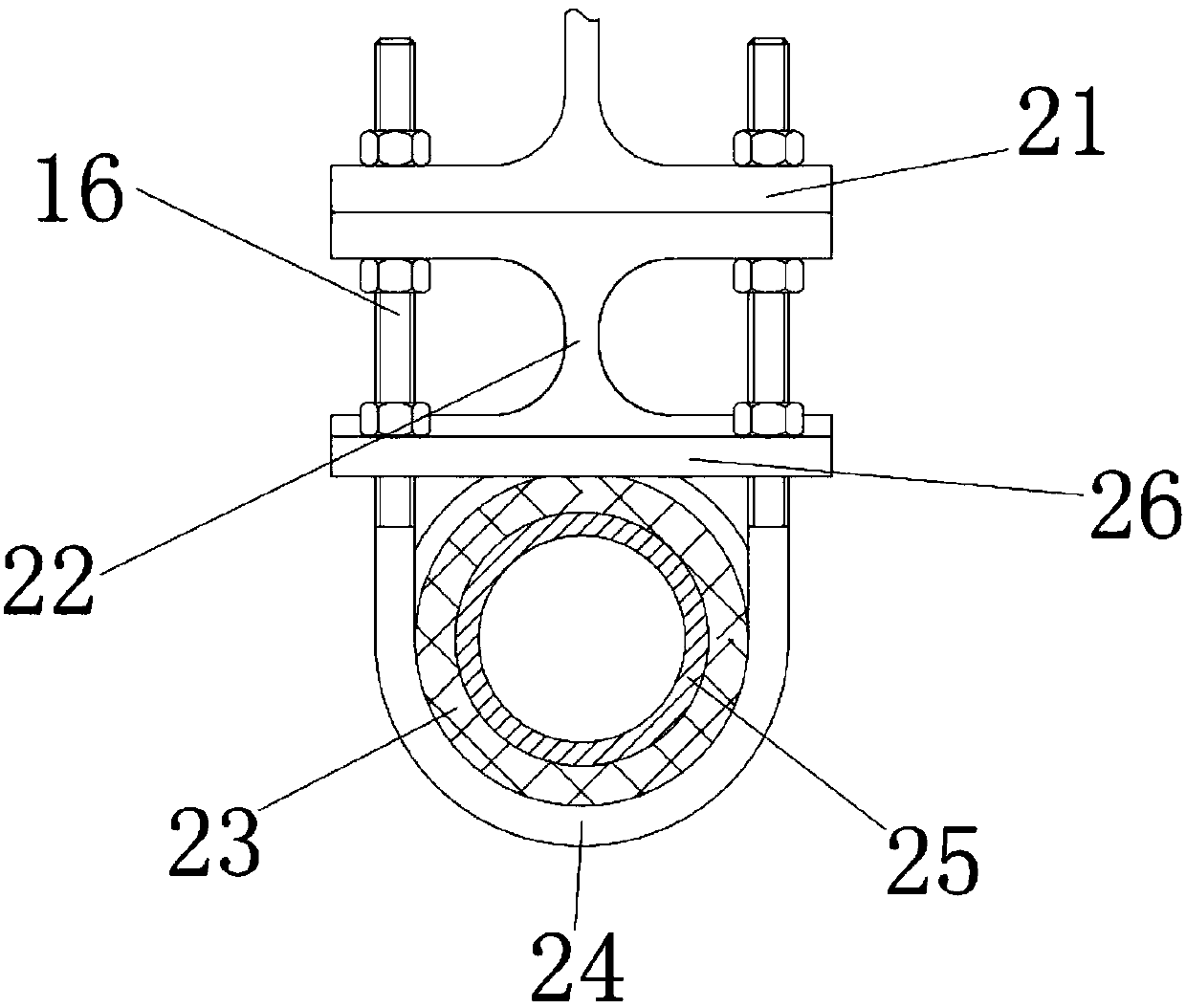
[0015] See Figure 1-3 , The present invention provides a technical solution: a building construction steel bar connection structure, including a base frame 1, the base frame 1 is made of stainless steel, used to install and fix the steel bar 14, the inner wall of the base frame 1 is installed with a pressure plate 2, the pressure plate 2 Tighten the steel bar 14, the outer wall of the pressure plate 2 is connected with the inner wall of...


PUM


Abstract

The invention discloses a steel bar connection structure for building construction. A pressing plate is installed on the inner wall of the bottom frame, and the outer wall of the pressing plate is connected with the inner wall of the bottom frame. A rubber pad is sleeved, the outer wall of the rubber pad is connected with the inner wall of the pole, the outer wall of the sleeve is connected with the inner wall of the pressing plate, and the inner wall of the pressing rod is connected with the outer wall of the sleeve. The steel bar connection structure of the house construction, through the cooperation between the bottom frame and the pressure plate, under the action of the pressure plate and the end cover, in addition, the use function of the telescopic boss is single, only one steel bar can be fixed, and the disadvantage of low efficiency is solved. The cooperation between the end cover, the spacer and the rubber pad improves the work efficiency, reduces the operation strength, has good oxidation resistance and corrosion resistance, prolongs the service life of the steel bar connection structure of the building construction, is easy to recycle, and avoids waste at the same time The construction and production costs are saved, and the invention is suitable for popularization and application.

Description

technical field [0001] The invention relates to the technical field of construction engineering, in particular to a steel bar connection structure for building construction. Background technique [0002] In the existing building structure, the grouting steel bar connection structure is mainly used. The steel bar connection is mainly connected and installed by bundling or sleeves. The bundling is wrapped with iron wire at the cross point of the steel bar. The disadvantage is that the iron wire is a product that is easy to corrode , after long-term thermal expansion and contraction and rain corrosion, it is easy to break, causing the steel bars to be disconnected from each other. The main disadvantages of the traditional sleeve connection are that it is difficult to manufacture and process, and the processing efficiency is low, and it is easy to leave gaps during the grouting process. Cause wall cracks, in the prior art, for example, the invention patent with application numbe...

Claims


Application Information

Patent Timeline
IPC IPC(8): E04C5/16
CPCE04C5/163E04C5/165
Inventor 肖亚玲
Owner CHENGDU LEYE TECH CO LTD
Why Eureka
Try Eureka