Inductive power transfer system and control method and control system therefor

A technology of inductive power transmission and circuits, applied in electrical components, circuit devices, output power conversion devices, etc., can solve the problems of inability to meet high-power wireless power transmission, transmission power limitations, etc., and achieve the effect of high-power power transmission.

Inactive Publication Date: 2018-03-23
SHANGHAI JIAO TONG UNIV
View PDF3 Cites 3 Cited by
  • Summary
  • Abstract
  • Description
  • Claims
  • Application Information

AI Technical Summary

Problems solved by technology

However, at this stage, most IPT systems use full-bridge inverters, and the transmission power is limited by the capacity of switching devices, which cannot meet the requirements of high-power wireless power transmission.

Method used


Image

  • Inductive power transfer system and control method and control system therefor
  • Inductive power transfer system and control method and control system therefor
  • Inductive power transfer system and control method and control system therefor

Examples


Embodiment 1

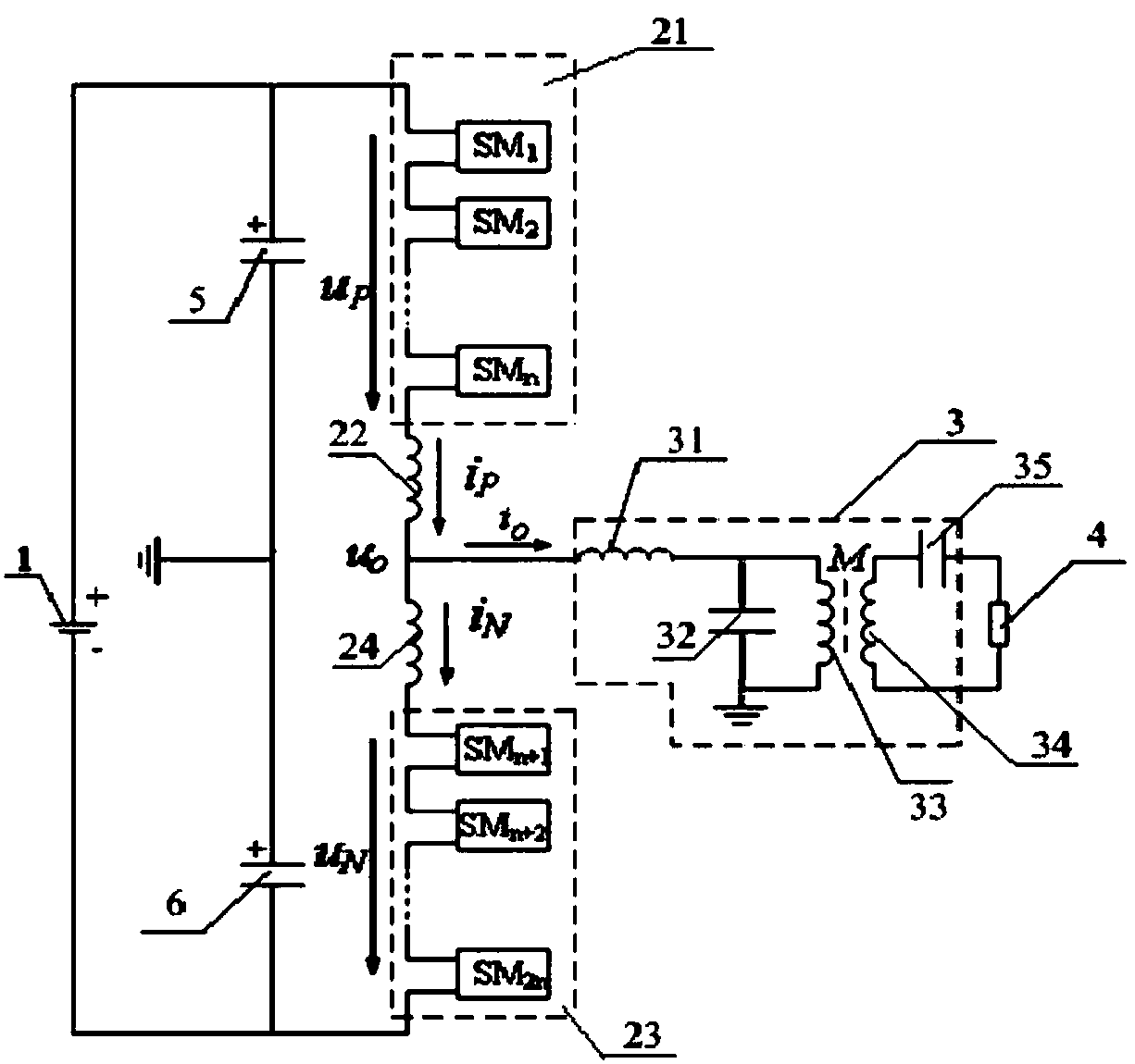
[0052] figure 1 This is a circuit diagram of the inductive power transmission system provided by Embodiment 1 of the present invention. Such as figure 1 As shown, an inductive power transmission system, the inductive power transmission circuit includes:

[0053] DC power module 1, modular multi-level inverter 2 and inductive power transmission module 3, of which,

[0054] The DC power supply module 1 is connected to the modular multilevel inverter 2, and the modular multilevel inverter 2 converts the DC power provided by the DC power supply module 1 into high frequency AC power, optionally , High-frequency AC voltage is an AC voltage with a frequency of 1kHz~25kHz;

[0055] The inductive power transmission module 3 is connected to the modular multilevel inverter 2, and the inductive power transmission module 3 is used to output the high-frequency AC voltage to the load 4 in the form of electromagnetic induction;

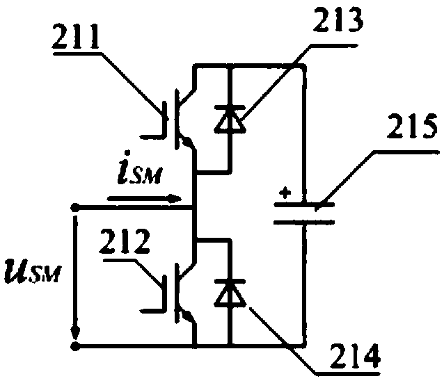
[0056] Wherein, the modular multi-level inverter 2 specifically includ...

Embodiment 2

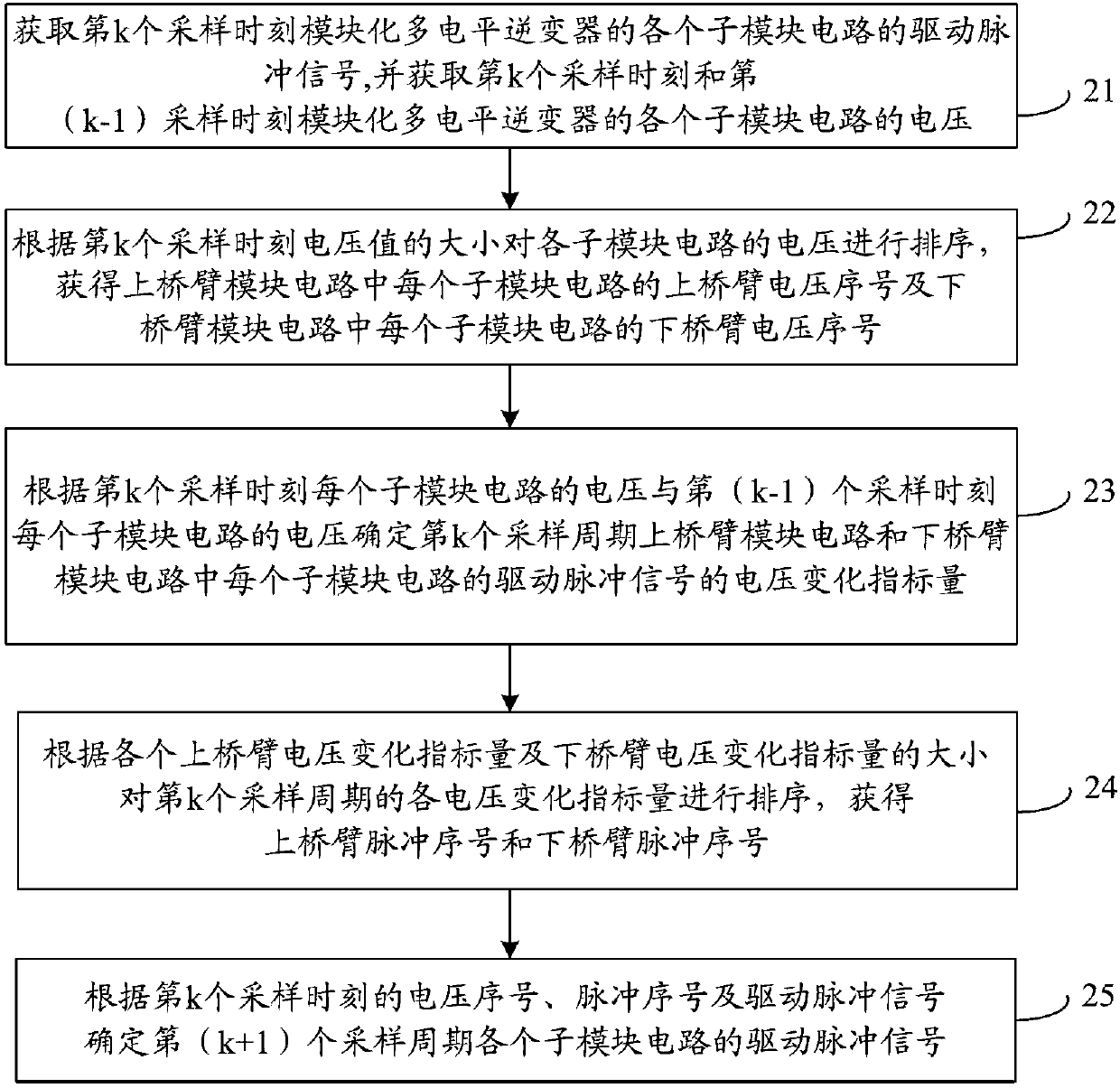
[0066] image 3 This is a flowchart of the control method provided by Embodiment 2 of the present invention. Such as image 3 As shown, a control method of an inductive power transmission system is used to control the modular multilevel inverter described in Embodiment 1, and the control method includes:

[0067] Step 21: Obtain the driving pulse signal of each sub-module circuit of the modular multilevel inverter at the kth sampling time, and obtain the kth sampling time and the (k-1)th sampling time of the modular multilevel inverse The voltage of each sub-module circuit of the converter, where the voltage of each sub-module circuit of the modular multi-level inverter at the 0th sampling time is 0;

[0068] Step 22: Sort the voltages of each sub-module circuit in the upper-side module circuit according to the magnitude of the voltage value at the kth sampling time to obtain the upper-side voltage sequence number of each sub-module circuit in the upper-side module circuit, and acc...

Embodiment 3

[0075] Figure 4 It is a structural block diagram of the control system provided by Embodiment 3 of the present invention. Such as Figure 4 As shown, a control system of an induction power transmission system is used to control the modular multilevel inverter described in Embodiment 1, and the control system includes:

[0076] The pulse signal acquisition module 31 is used to acquire the driving pulse signal of each sub-module circuit of the modular multilevel inverter at the kth sampling time;

[0077] The sub-module voltage obtaining module 32 is used to obtain the voltage of each sub-module circuit of the modular multilevel inverter at the kth sampling time and the (k-1)th sampling time, where the 0th sampling time is modular The voltage of each sub-module circuit of the multi-level inverter is 0;

[0078] The voltage sequence number determining module 33 is used to sort the voltages of the sub-module circuits in the upper-side module circuit according to the magnitude of the vo...


PUM


Abstract

The invention discloses an inductive power transfer system and a control method and control system therefor. An inductive power transfer circuit comprises a direct current power supply module, a modular multi-level inverter and an inductive power transfer module; the direct current power supply module is connected with the modular multi-level inverter; the modular multi-level inverter converts a direct current provided by the direct current power supply module into a high-frequency alternating current; the inductive power transfer module is connected with the modular multi-level inverter; andthe inductive power transfer module is used for outputting the high-frequency alternating current voltage to a load in an electromagnetic induction form. The modular multi-level inverter-based inductive power transfer system provided by the invention belongs to the high-frequency power transfer system, so that high-power power transfer can be realized; and in addition, the modular multi-level inverter has a common direct current bus, so that installation of an independent direct current power supply in each sub module is not needed, thereby greatly reducing the size of the apparatus and lowering the cost of the inductive power transfer system.

Description

Technical field [0001] The invention relates to the field of inductive power transmission, in particular to an inductive power transmission system and its control method and control system. Background technique [0002] Inductive Power Transfer (IPT) technology realizes non-contact energy transmission through electromagnetic induction, overcomes the shortcomings of traditional power transmission technology such as sparks and carbon deposits, and has been widely used in many fields. However, most IPT systems currently use full-bridge inverters, and the transmission power is limited by the capacity of switching devices, which cannot meet the requirements for high-power wireless power transmission. [0003] Therefore, how to increase the transmission power of the IPT system has become an urgent technical problem for those skilled in the art. Summary of the invention [0004] The purpose of the present invention is to provide an inductive power transmission system and its control metho...

Claims


Application Information

Patent Timeline
IPC IPC(8): H02M7/483H02M7/5387H02M7/5395H02J50/12
CPCH02M7/483H02M7/53871H02M7/5395H02J50/12H02M7/4835
Inventor 姚钢周荔丹
Owner SHANGHAI JIAO TONG UNIV
Why Eureka
Try Eureka