
Automatic light tracking power generation device

A power generation device, automatic technology, applied in the direction of photovoltaic power generation, photovoltaic modules, electrical components, etc., can solve the problems of poor power generation efficiency, difficult for solar panels to face the sun, measurement differences, etc., to achieve direct steering movement process, cost and maintenance. Low cost, easy to manufacture and maintain

Inactive Publication Date: 2018-03-23
林作伟
View PDF5 Cites 4 Cited by
  • Summary
  • Abstract
  • Description
  • Claims
  • Application Information

AI Technical Summary

Problems solved by technology

[0002] In the prior art, solar power generation devices mostly adopt the method of fixing solar panels, so that the solar panels have only one direction from beginning to end. Since the position of the sun changes from east to west during the day, the solar power of this type of solar power generation device has The panels cannot face the sun all the time, resulting in poor power generation efficiency
[0003] For this reason, people have proposed various improved schemes, trying to allow solar panels to face the sun at all times without artificial movement, so as to achieve the maximum power generation benefit, but the solar power generation in this way in the prior art There are still various problems with the device
[0004] At present, among the devices that automatically track the position of the sun, some use the apparent solar movement trajectory to track. It confirms the current orientation of the sun based on the precise local latitude and longitude and the precise sun trajectory algorithm. It needs to connect to the network to confirm the current time and pass The global positioning system confirms the current latitude and longitude, which not only consumes a lot of power generation, but also complicates the system settings; some use photoelectric tracking, and use photoresistors to compare the light intensity in different directions to confirm the strongest light to confirm the current orientation of the sun. It is technically simpler, and the cost of manufacture and use is also lower. It is accepted by people and is willing to be actively developed.
[0005] Usually, in order to keep the solar panel facing the sun at all times, people use motion to adjust the position and orientation of the solar panel by rotating or swinging. However, only relying on rotation or swinging cannot make the solar panel face the sun directly. In the process, there is also how to move quickly and accurately and adjust to the position and orientation of the sun
[0006] In addition, photoresistors are generally fixed on different sides of the solar panel to detect the intensity of light on different sides. However, due to the long distance between them, the difference in light intensity experienced by them is obvious, which may easily cause differences in measurement. Make it difficult for solar panels to face the sun

Method used


Image

  • Automatic light tracking power generation device
  • Automatic light tracking power generation device
  • Automatic light tracking power generation device

Examples


Embodiment Construction

[0025] The present invention is described in detail below in conjunction with accompanying drawing:

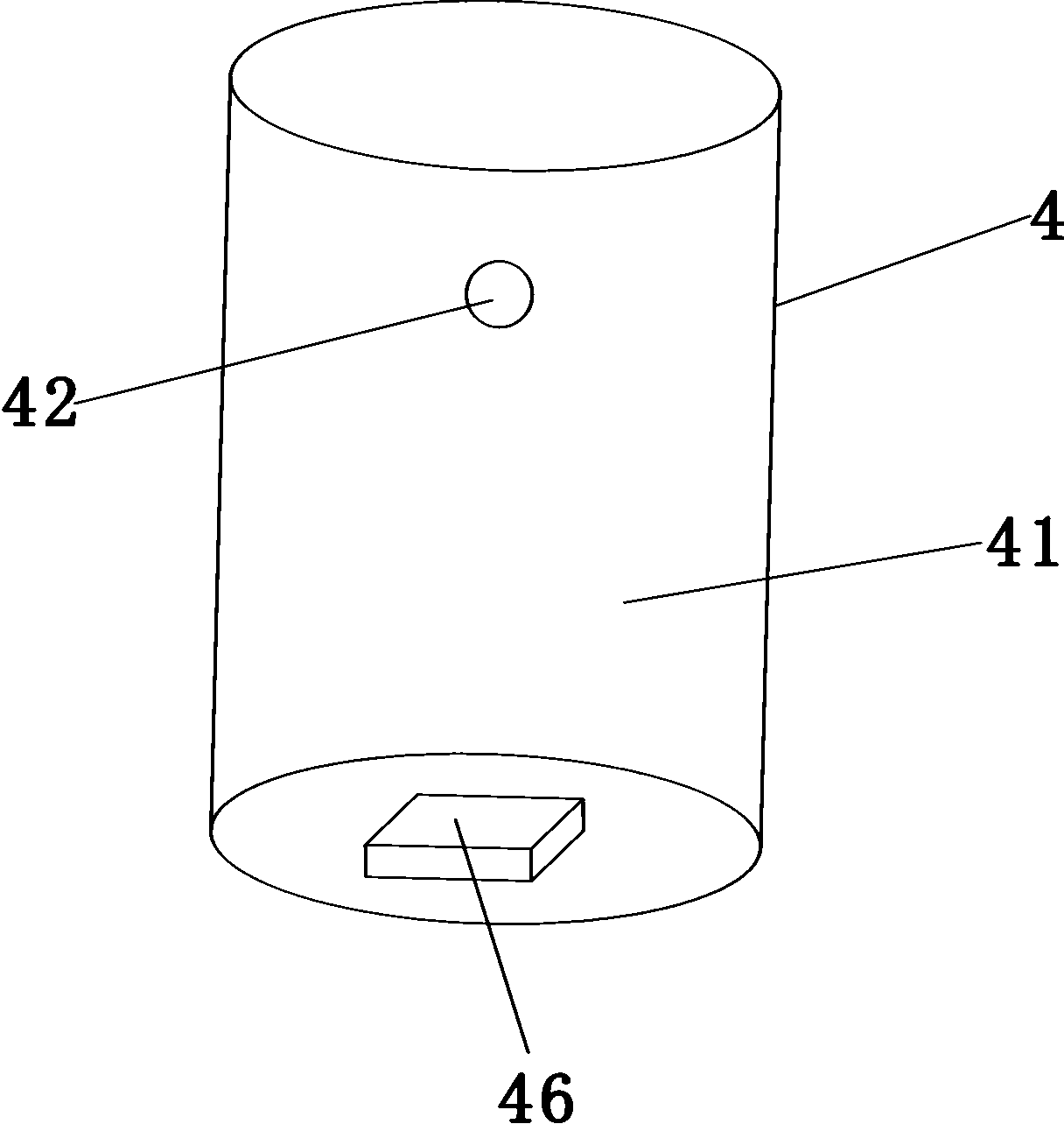
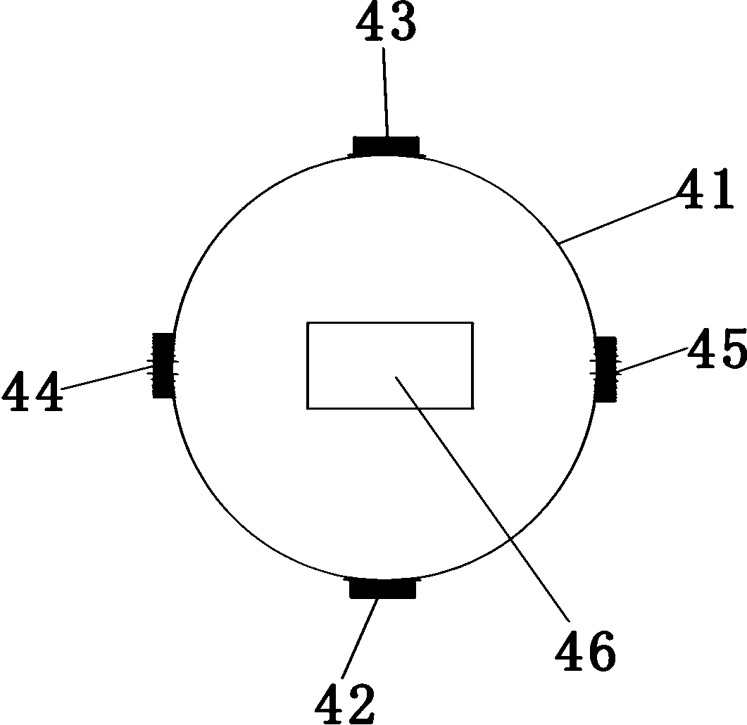
[0026] refer to figure 2 and image 3 , the photoresistor probe 4 includes a housing 41 made of opaque and heat-resistant materials, and the four photoresistors 42, 43, 44, 45 are divided into two groups (42, 43), (44, 45) and are relatively installed on the On the casing 41, and the four photoresistors 42, 43, 44, 45 are respectively facing the four surrounding directions, and the middle of the casing is filled with an opaque material (not shown in the figure), and the four photoresistors 42, 43, 44 The lead wires of , 45 are drawn from the inside of the housing to the through hole 46 at the end of the housing (not shown in the figure).

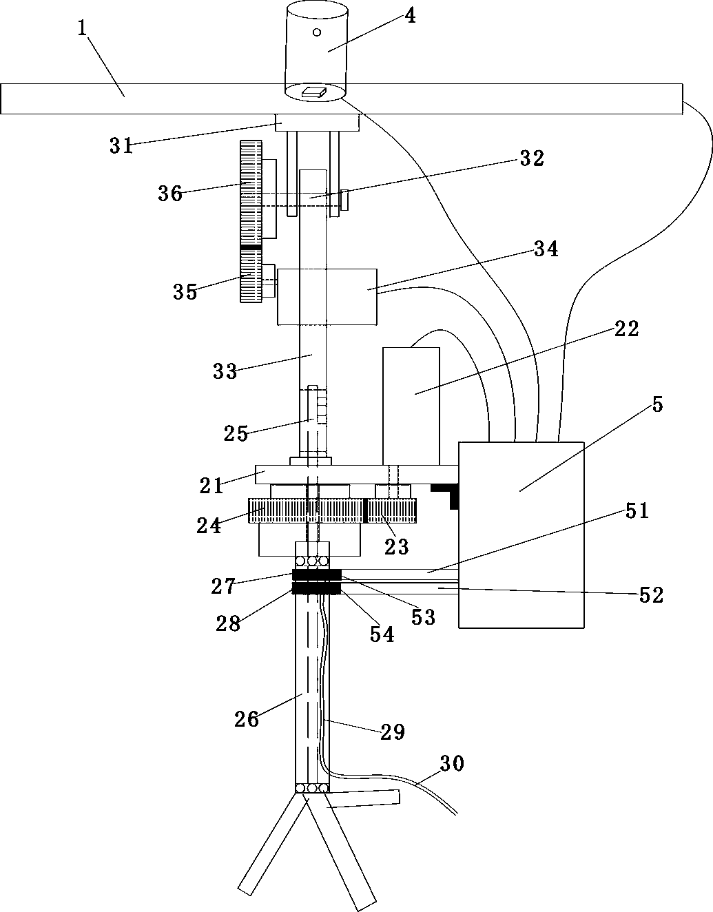
[0027] refer to figure 1 , the automatic light-following power generation device of the specific embodiment includes a solar panel 1, a left and right rotation mechanism 2, an up and down swing head mechanism 3, a photoresistor probe 4 a...


PUM


Abstract

The invention discloses an automatic light tracking power generation device. The automatic light tracking power generation device comprises a solar panel, a left-and-right rotation mechanism, an up-and-down swing mechanism, two groups of photosensitive resistors and a main control box; the up-and-down swing mechanism is fixed on the left-and-right rotation mechanism; the solar panel is installed on the up-and-down swing mechanism; the two groups of photosensitive resistors are oppositely installed on the solar panel; the control circuit of the main control box controls the left-right rotationmechanism and the up-and-down swing mechanism according to signals provided by the two groups of photosensitive resistors; and the left-and-right rotation mechanism and the up-and-down swing mechanismdrive the solar panel to rotate and swing. According to the device, the solar panel can move quickly and face the sun, so that power generation efficiency can be maximized.

Description

technical field [0001] The invention belongs to a solar power generation device, and relates to an improvement for adjusting the direction of a solar panel according to the intensity of light, more specifically, a solar power generation device capable of automatically tracking light. Background technique [0002] In the prior art, solar power generation devices mostly adopt the method of fixing solar panels, so that the solar panels have only one direction from beginning to end. Since the position of the sun changes from east to west during the day, the solar power of this type of solar power generation device has The panels cannot face the sun all the time, resulting in poor power generation efficiency. [0003] For this reason, people have proposed various improved schemes, trying to allow solar panels to face the sun at all times without artificial movement, so as to achieve the maximum power generation benefit, but the solar power generation in this way in the prior art ...

Claims


Application Information

Patent Timeline
IPC IPC(8): H02S20/32G05D3/12F24S50/20
CPCG05D3/12H02S20/32Y02E10/50
Inventor 林作伟
Owner 林作伟
Learn More