Al technical title is built by PatSnap Al team. It summarizes the technical point description of the patent document.
A cold-chamber die-casting and machine base technology, applied in the field of cold-chamber die-casting machines, can solve problems such as slowing down the manufacturing speed of castings, physical damage to operators, and reduced production efficiency, and achieve compact structure, good economic and social benefits, and improved efficiency effect
Active Publication Date: 2018-03-27
嘉瑞金属制品(深圳)有限公司
View PDF7 Cites 4 Cited by
Summary
Abstract
Description
Claims
Application Information
AI Technical Summary
This helps you quickly interpret patents by identifying the three key elements:
Problems solved by technology
Method used
Benefits of technology
Problems solved by technology
With the advancement of science and technology and industrial production, especially with the development of industries such as automobiles, motorcycles, and household appliances, die-casting technology has developed extremely rapidly in various aspects. Die-casting machines are divided into hot-press chamber die-casting machines and cold-press There are two types of chamber die-casting machines. Most of the existing cold die-casting machines use natural cooling to cool the castings. This cooling method takes too long, slows down the manufacturing speed of castings, and greatly reduces production efficiency. At the same time, die-casting After forming, workers need to go deep into the mold to take out the casting, so sometimes the temperature of the finished product may not be completely reduced to a harmless level, which will cause damage to the operator's body, and it is very difficult to take out the casting directly from the mold
Method used
Image
Click on the blue label to locate the original text in one second.
Reading with bidirectional positioning of images and text.
Examples
Embodiment Construction
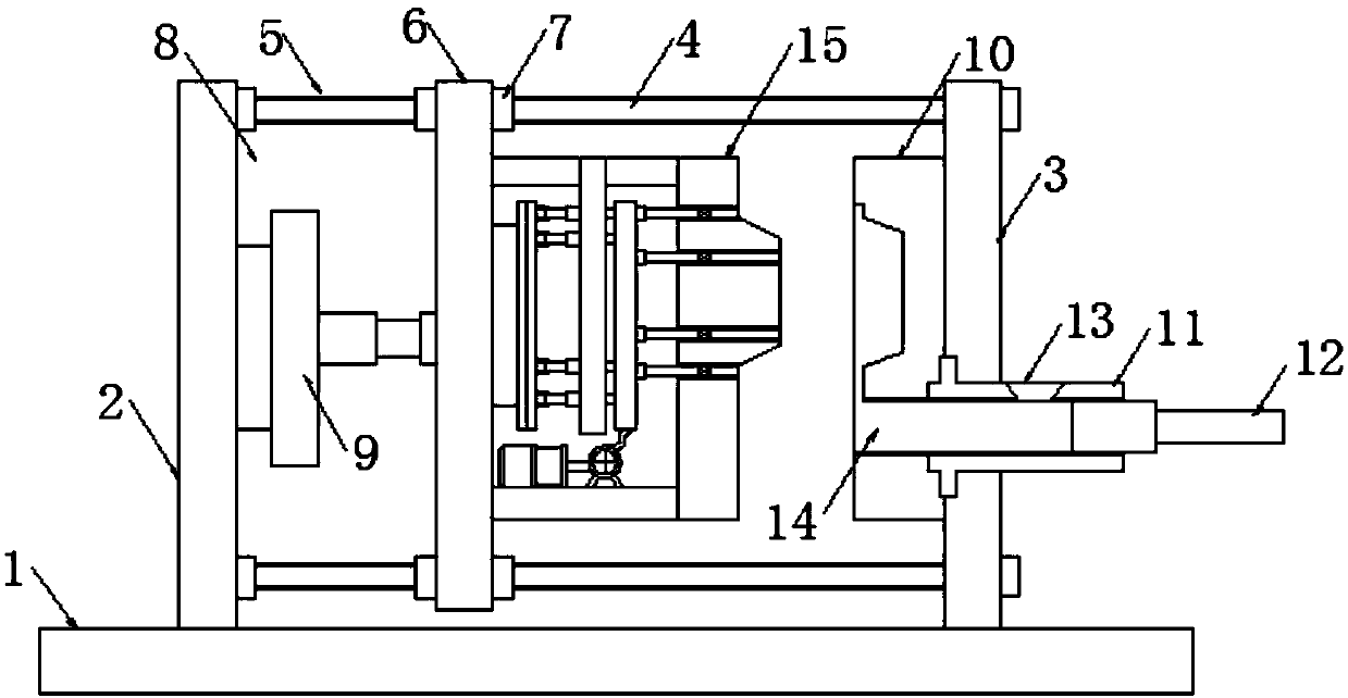
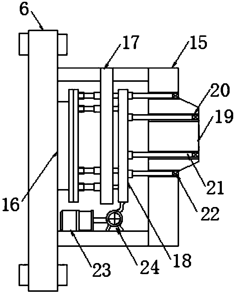
[0021] like Figure 1-3 As shown, this specific embodiment adopts the following technical solutions: a cold chamber die-casting machine, including a machine base 1, a first mounting frame 2 is fixed on the machine base 1, and the machine base 1 on one side of the first mounting frame 2 is fixedly installed There is a second mounting frame 3, and the first mounting frame 2 and the second mounting frame 3 are arranged correspondingly. There is a slide rail 5, the guide post 4 passes through the traverse slide plate 6, and the traverse slide plate 6 is slidably connected with the guide post 4 through the sliding sleeve 7 provided thereon, and a squeeze is formed between the first installation frame 2 and the traverse slide plate 6. The pressure chamber 8, and the die-casting cylinder 9 is fixedly installed on the first installation frame 2 in the extrusion chamber 8, and the die-casting cylinder 9 is connected with the traverse slide plate 6 through its output end.
[0022] Wher...
PUM
Abstract
The invention discloses a cold-chamber die casting machine which comprises a machine seat, a first mounting frame, a second mounting frame, guiding columns, sliding rails, a transverse-moving slidingplate, sliding sleeves, a squeezing cavity, a die casting air cylinder, a concave die plate, a liquid inlet pipe, a supercharging piston, a liquid inlet pipe orifice, a material filling hole, a convexdie block, an ejecting air cylinder, a positioning partition plate, an ejecting plate, a convex die main body plate, through holes, ejecting pins, sealing vales, a high-pressure air pump, a cooler and a concave surface plate. The cold-chamber die casting machine disclosed by the invention is compact in structure and convenient to use; by adoption of the structural design that an ejecting device is additionally arranged on the convex die plate, a casting can be directly ejected, the trouble that the casting needs to be directly taken by people out of a die can be avoided, the die casting efficiency can be improved, and the personal safety of an operating worker can be guaranteed; through high-pressure cooling airflow jetted from air ports of the ejecting pins, a finished workpiece can be quickly cooled, the cooling speed in a die casting process of the workpiece can be improved, and the more uniform cooling effect can be achieved; and meanwhile, waste scraps on the workpiece can be effectively removed and the quality of a finished die casting product can be improved.
Description
technical field [0001] The invention relates to the technical field of die-casting machines, in particular to a cold-chamber die-casting machine. Background technique: [0002] The die-casting machine is a series of industrial casting machines that hydraulically inject molten metal into the mold under pressure to cool and form it, and obtain solid metal castings after the mold is opened. It was originally used for die-casting characters. With the advancement of science and technology and industrial production, especially with the development of industries such as automobiles, motorcycles, and household appliances, die-casting technology has developed extremely rapidly in various aspects. Die-casting machines are divided into hot-press chamber die-casting machines and cold-press There are two types of chamber die-casting machines. Most of the existing cold die-casting machines use natural cooling to cool the castings. This cooling method takes too long, slows down the manufac...
Claims
Application Information
Patent Timeline
Application Date:The date an application was filed.
Publication Date:The date a patent or application was officially published.
First Publication Date:The earliest publication date of a patent with the same application number.
Issue Date:Publication date of the patent grant document.
PCT Entry Date:The Entry date of PCT National Phase.
Estimated Expiry Date:The statutory expiry date of a patent right according to the Patent Law, and it is the longest term of protection that the patent right can achieve without the termination of the patent right due to other reasons(Term extension factor has been taken into account ).
Invalid Date:Actual expiry date is based on effective date or publication date of legal transaction data of invalid patent.