
Electric power assisted wheel

A power-assisted wheel and electric technology, which is applied in the field of wheels, can solve the problems of bicycle modification and poor use effect, increase the weight of bicycles, and lack of versatility, etc., and achieve the effect of light and fast wheels, ensuring stable work, and reducing vibration

Active Publication Date: 2018-03-27
KAIFENG UNIV
View PDF9 Cites 1 Cited by
  • Summary
  • Abstract
  • Description
  • Claims
  • Application Information

AI Technical Summary

Problems solved by technology

[0002] At present, there are a large number of traditional bicycles on the market, but the development of electric vehicles has caused bicycles to be gradually not sought after by people, and can no longer meet people's needs; people refit bicycles in an attempt to make them electric bicycles, but there are various ways of refitting; The structure of the refitted car is complicated, and the body is unstable, causing potential safety hazards; some add batteries to the bicycle, which increases the weight of the bicycle, and is extremely inconsistent with the body; Bicycles are not versatile, making the modification and use of bicycles less effective

Method used


Image

  • Electric power assisted wheel
  • Electric power assisted wheel
  • Electric power assisted wheel

Examples


Embodiment 1

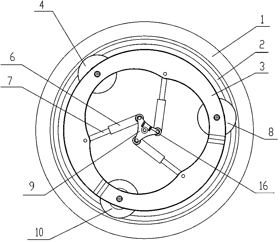
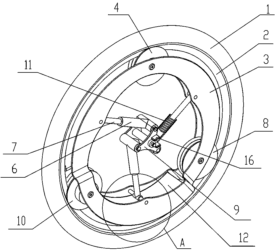
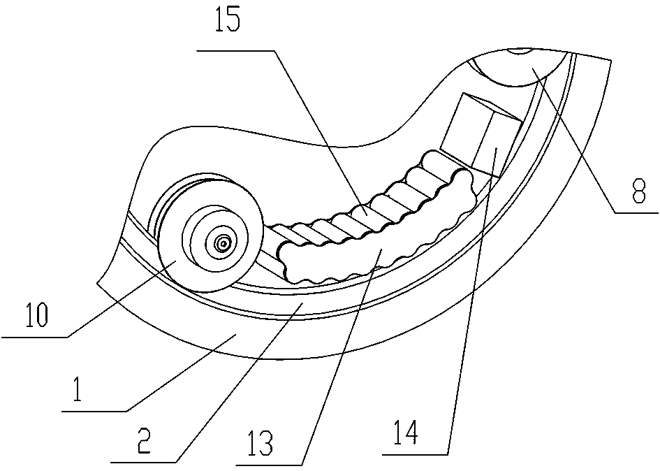
[0023] Embodiment 1: as Figure 1~Figure 5 As shown, an electric power-assisted wheel includes a wheel body, the wheel body includes a tire 1, a rim 2 and a side plate 3, the tire 1 is a non-inflatable rubber tire; the inner side of the tire 1 closely fits the rim 2. The cross section of the rim 2 is "T" shape, and the inner ring of the rim 2 is equipped with gears; the inner sides of the rim 2 are respectively equipped with side plates 3, and the side plates 3 are three-petal flower-shaped inner rings, The outer ring is circular, and the first fixed pulley 4, the second fixed pulley 8 and the brushless motor 10 are connected by bolts between the two side plates 3. The first fixed pulley 4, the second fixed pulley 8 and the brushless motor The brush motors 10 are round cakes with a circular through hole in the center and a groove on the side of the outer ring. The angle between the first fixed pulley 4, the second fixed pulley 8 and the brushless motor 10 is 12°. °; the groov...

Embodiment 2

[0025] Embodiment 2: Embodiment 2 has basically the same structure as Embodiment 1, and the similarities will not be repeated. The difference is: the outer surface of the tire is provided with tread patterns, and the tread patterns are block patterns; Draw; the tread pattern can increase the force-bearing area of ​​the electric power-assisted wheel, reduce the pressure on the ground, roughen the contact surface of the electric power-assisted wheel, and increase beneficial friction.


PUM


Abstract

The invention discloses an electric power assisted wheel which comprises a wheel body. The wheel body comprises a tire, a rim and side plates, the inner side of the tire closely fits the rim, and gears are distributed on the inner periphery of the rim. The side plates are distributed on two inner sides of the rim, the inner periphery of each side plate is in a three-petal flower shape while the outer periphery of each side plate is circular, a first fixed pulley, a second fixed pulley and a brushless motor are connected between the two side plates through bolts, and tooth structures meshed with the gears on the inner periphery of the rim are uniformly distributed in grooves of the first fixed pulley, the second fixed pulley and the brushless motor. A battery storage cavity with a cover isformed between the two side plates between the second fixed pulley and the brushless motor, and a damping device is arranged in each side plate and comprises a damping rod, a damping rod outer sleeveand a connection plate, a rotating shaft at the upper end of each damping rod outer sleeve is connected with a connection plate, and two parallel retaining plates are vertically arranged on each connection plate. The electric power assisted wheel has advantages of quickness in mounting, convenience, flexibility and wide suitability.

Description

technical field [0001] The invention relates to the technical field of wheels, in particular to an electric power-assisted wheel. Background technique [0002] At present, there are a large number of traditional bicycles on the market, but the development of electric vehicles has caused bicycles to be gradually not sought after by people, and can no longer meet people's needs; people refit bicycles in an attempt to make them electric bicycles, but there are various ways of refitting; The structure of the refitted car is complicated, and the body is unstable, causing potential safety hazards; some add batteries to the bicycle, which increases the weight of the bicycle, and is extremely inconsistent with the body; The bicycle does not have versatility, so that the modification and use effect of the bicycle is poor. Therefore, the present invention designs an electric power-assisted wheel, is used for the refitting of bicycle, to solve the problem that runs into in the above-m...

Claims


Application Information

Patent Timeline
Patent Type & Authority Applications(China)
IPC IPC(8): B62M7/12B60B19/00
CPCB62M7/12B60B19/00
Inventor 李辉
Owner KAIFENG UNIV
Learn More