Glass sheet stacking rack

A technology for stacking racks and glass sheets, which is applied to conveyor objects, furnaces, lighting and heating equipment, etc., to achieve stable transmission, prevent unreliable coordination, and simple structure.

Inactive Publication Date: 2018-03-27
CHENGDU YANXINGGUO TECH CO LTD
View PDF0 Cites 0 Cited by
  • Summary
  • Abstract
  • Description
  • Claims
  • Application Information

AI Technical Summary

Problems solved by technology

[0004] The object of the present invention is: in order to solve the problem of dust removal on the glass surface, the present invention provides a glass sheet stacking rack

Method used


Image

  • Glass sheet stacking rack
  • Glass sheet stacking rack

Examples


Embodiment 1

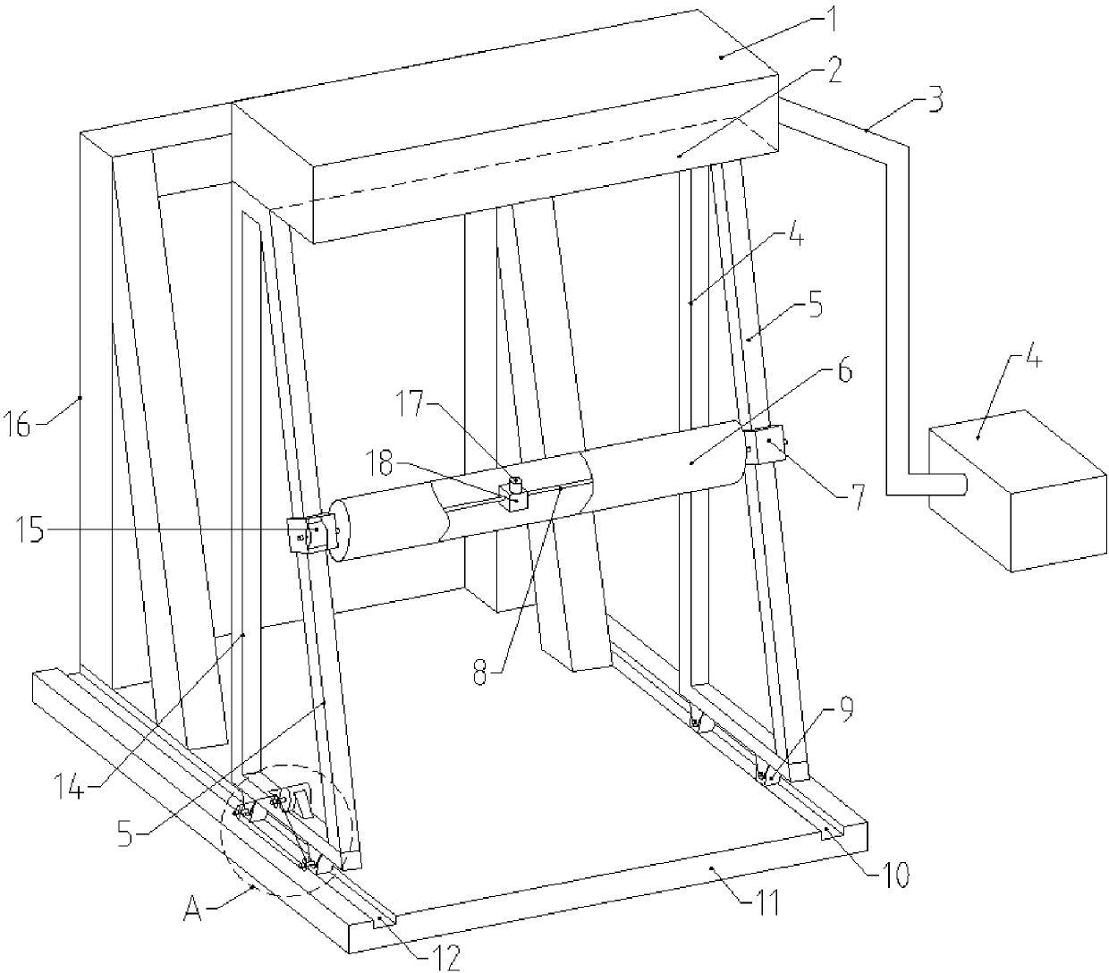
[0020] A glass sheet stacking rack, comprising a bottom plate 11 provided with a support frame 16, characterized in that: the upper surface of the bottom plate 11 is respectively provided with a guide groove a12 and a guide groove b10 on the left and right sides of the support frame 16, and the guide groove a12 and the guide groove b10 There are L-shaped sliding bracket a14 and sliding bracket b4 respectively, the sliding bracket a14 is provided with a power device 13, the height of sliding bracket a14 and sliding bracket b4 is higher than that of the supporting frame 16, the top of sliding bracket a14, sliding bracket b14 and The racks 5 are connected to the bottom ends obliquely, and the rotating shaft 8 sleeved with the cleaning roller 6 is arranged horizontally between the sliding bracket a14 and the sliding bracket b4. Both ends of the rotating shaft 8 cooperate with the rack 5 through the gear 15, and the rotating shaft 8 passes through The transmission mechanism 18 is co...

Embodiment 2

[0024] This embodiment improves on the basis of Embodiment 1:

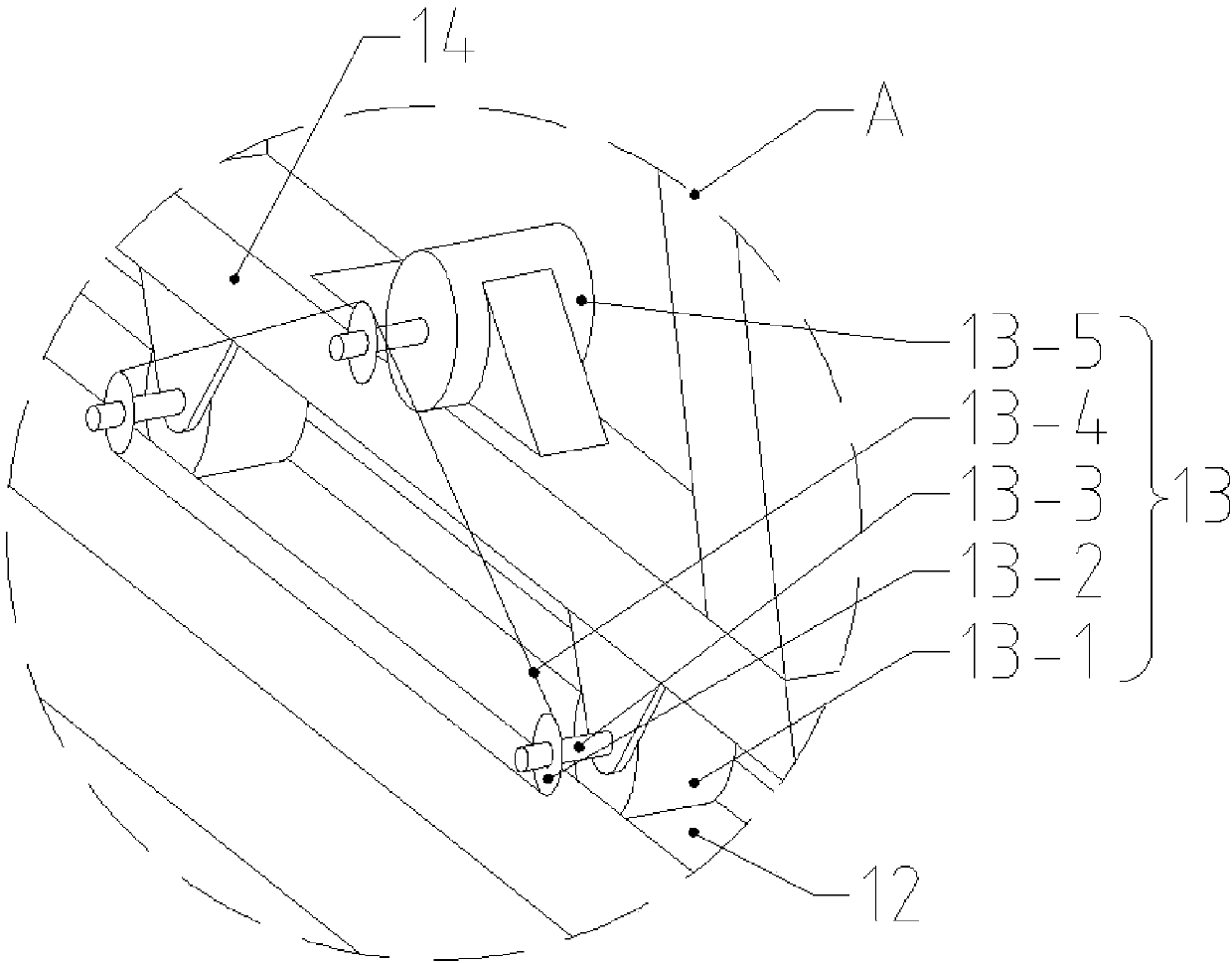
[0025] The power unit 13 includes a plurality of driving shafts 13-3 that are provided with driving rollers 13-1, the driving shafts 13-3 are arranged at the bottom of the sliding bracket a14, the driving rollers 13-1 are in contact with the guide groove a12, and the driving shafts 13-1 3 ends are provided with several identical sprocket wheels 13-2, and the sprocket wheels 13-2 are connected with the active motor 13-5 arranged on the sliding bracket a14 through the chain 13-4, and the bottom end of the sliding bracket b4 is provided with a number of guide motors. The groove b10 contacts the mating driven roller 9 .

[0026] The advantages of the above improvements are that the driving motor drives the driving roller by utilizing the cooperation of the sprocket and the chain, the transmission of the sprocket and the chain is stable, and the structure is simple.

Embodiment 3

[0028] This embodiment is improved on the basis of the above embodiments:

[0029] The transmission mechanism 18 is a worm gear mechanism, the gear 15 is arranged in the sliding box 7 , and the sliding box 7 is movably sleeved on the rack 5 .

[0030] The advantages of the above improvements are: the worm and worm mechanism is self-locking, preventing the cleaning roller from being damaged by falling along the rack under the action of gravity. At the same time, a sliding box is set on the rack, and the sliding box and the rack are clamped and pressed together. Gears prevent the gears from being loosely matched with the rack.


PUM


Abstract

The invention discloses a glass sheet stacking rack and relates to the technical field of glass processing. Through the glass sheet stacking rack, the problem of dust removal of the glass surface is solved. The glass sheet stacking rack comprises a bottom plate. A supporting frame is arranged on the bottom plate. Guide grooves are formed in the upper surface of the bottom plate and located on thetwo sides of the supporting frame correspondingly. A sliding support is arranged on each guide groove. A rack is obliquely arranged on each sliding support. The bottom end of each sliding support is provided with a power unit matched with the corresponding guide groove. A rotary shaft sleeved with a cleaning roller is arranged between the sliding supports on the two sides. The two ends of the rotary shaft are matched with the racks through gears. The rotary shaft is connected with a motor a through a transmission mechanism. According to the glass sheet stacking rack, the power units are used for driving the corresponding sliding supports to slide; the cleaning roller moves up and down through cooperation of the gears and the corresponding racks; dust adsorbed to any place of a glass sheetcan be fully cleaned.

Description

technical field [0001] The invention relates to the technical field of glass processing, in particular to a glass sheet stacking rack. Background technique [0002] Glass is formed by melting silicon dioxide and other chemical substances (the main production raw materials are: soda ash, limestone, quartz), forming a continuous network structure during melting, and the viscosity gradually increases during cooling and hardens to cause it to crystallize silicon Salt non-metallic materials. Because glass has high hardness and good light transmission, it has been widely used in our daily life, such as glass doors and windows of houses, car glass windows, various glass crafts and various optical instruments. [0003] At present, glass loading machines using vacuum suction cups have been widely used in glass production. Using the suction force generated after vacuuming inside the suction cups, the glass sheets are adsorbed and fixed for glass sheet loading. Often, during the produ...

Claims


Application Information

Patent Timeline
Patent Type & Authority Applications(China)
IPC IPC(8): B65G49/06
CPCB65G49/062
Inventor 魏霁烁
Owner CHENGDU YANXINGGUO TECH CO LTD
Why Eureka
Try Eureka