Variable valve lift mechanism, method for controlling valve lift and engine

A valve lift, engine technology, applied in the direction of machines/engines, engine components, mechanical equipment, etc., can solve problems such as high engine noise, reduce noise, improve user experience, and reduce the risk of engine failure.

Active Publication Date: 2018-03-27
WEICHAI POWER CO LTD
View PDF6 Cites 4 Cited by
  • Summary
  • Abstract
  • Description
  • Claims
  • Application Information

AI Technical Summary

Problems solved by technology

[0006] The purpose of the present invention is to propose a variable valve lift mechanism, a method for controlling the valve lift and an engine, which can solve the problem of high noise when the engine is switched between high and low speeds in the prior art

Method used


Image

  • Variable valve lift mechanism, method for controlling valve lift and engine
  • Variable valve lift mechanism, method for controlling valve lift and engine
  • Variable valve lift mechanism, method for controlling valve lift and engine

Examples


Embodiment 1

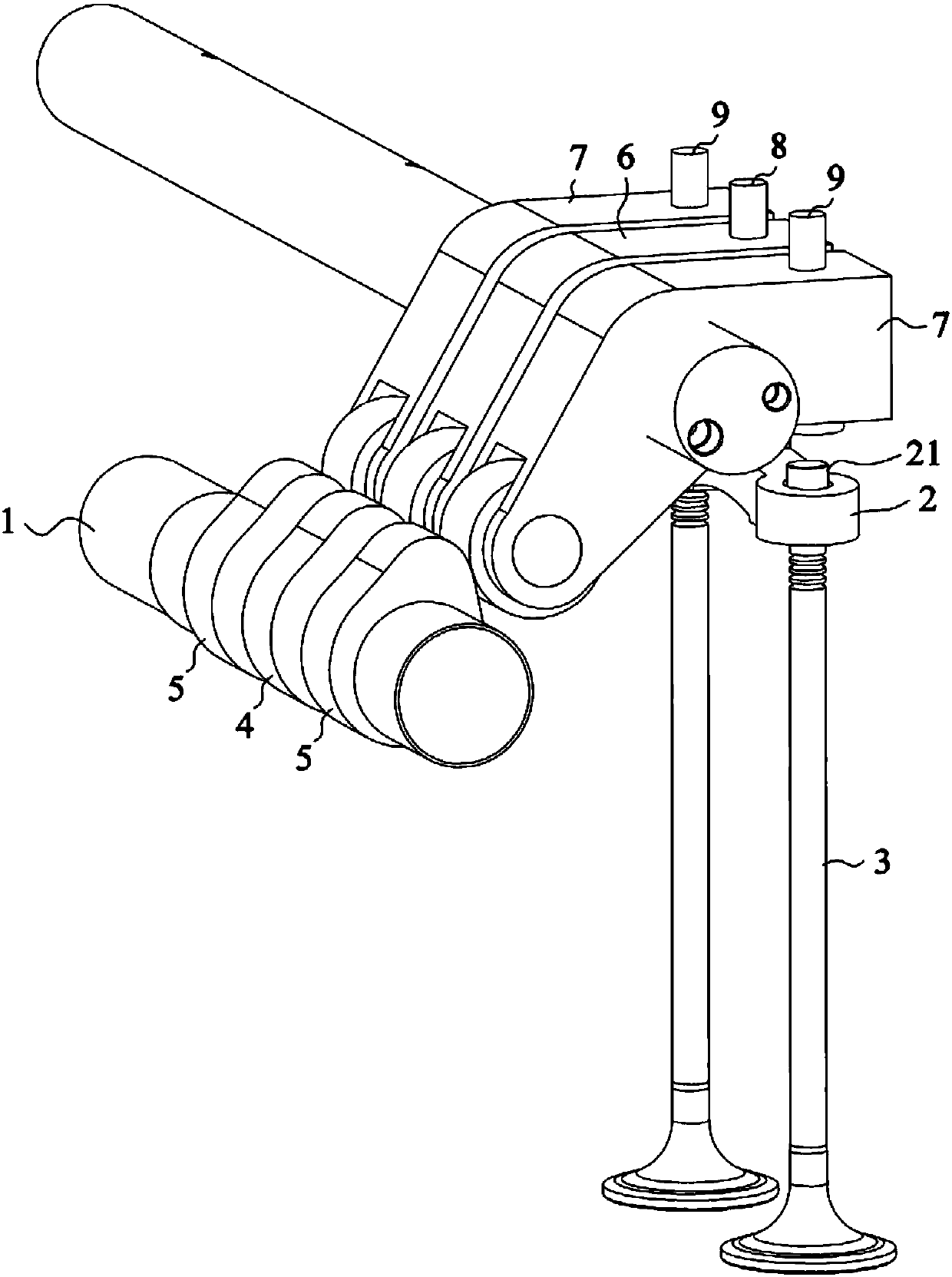
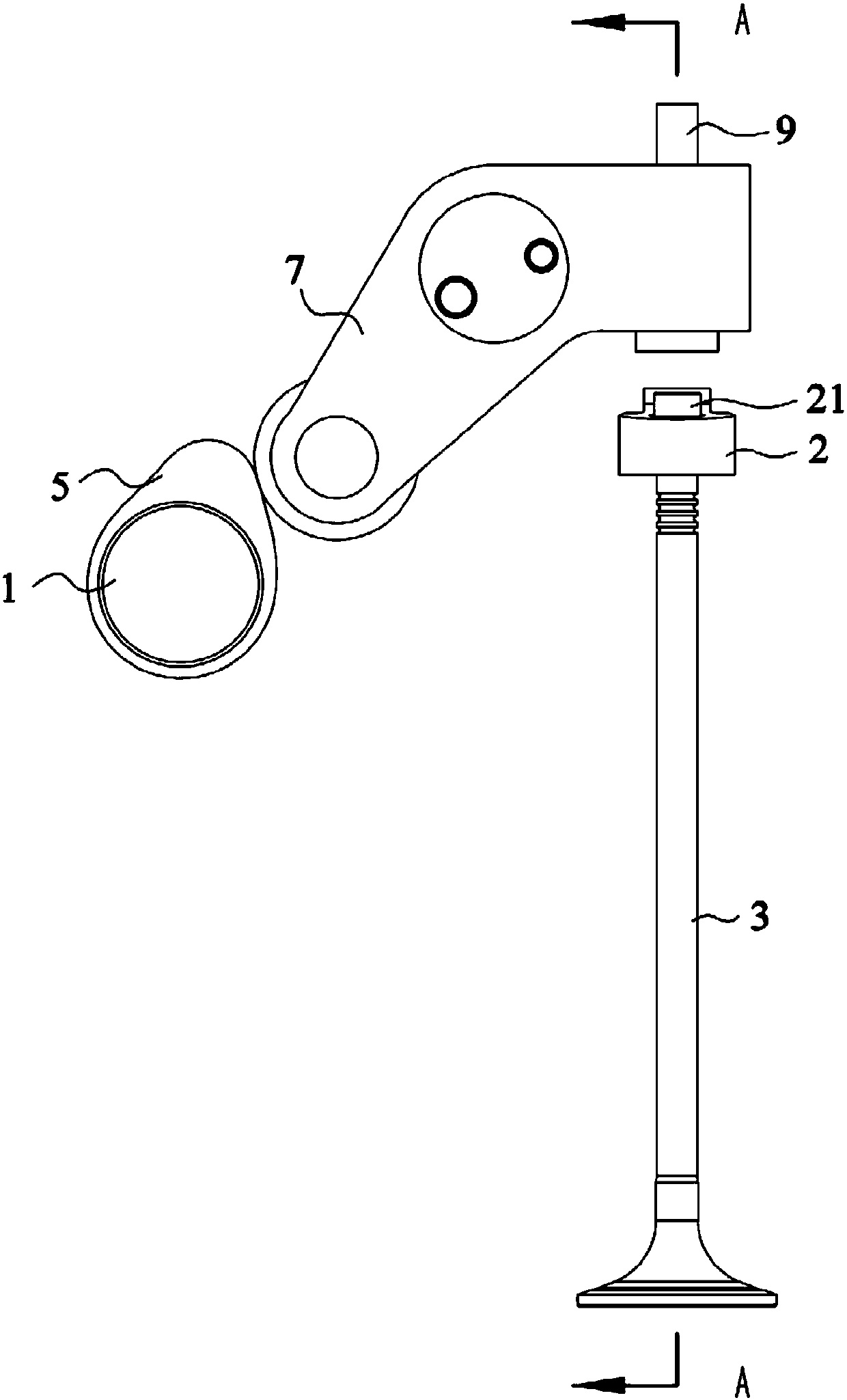
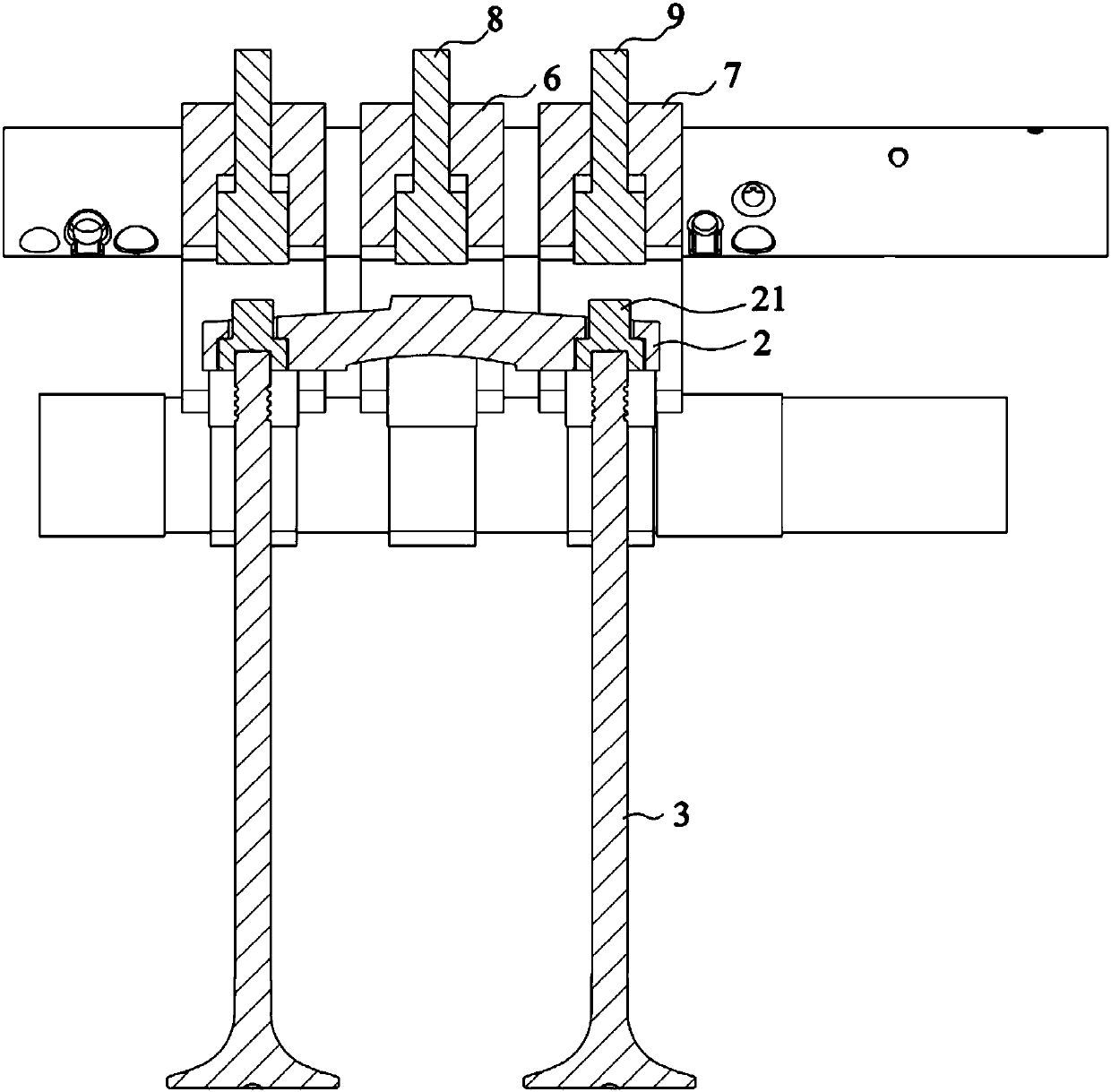
[0031] see figure 1 with figure 2 , the present embodiment provides a variable valve lift mechanism, including a camshaft 1, a valve bridge 2 and two valves 3, a valve bridge 2 is connected between the two valves 3, and both ends of the valve bridge 2 are provided with actuators pin 21.

[0032] The variable valve lift mechanism also includes a first cam 4 and a second cam 5, the two second cams 5 are located on both sides of the first cam 4, and the first cam 4 and the two second cams 5 are all arranged on the camshaft 1 and acts on one end of the first rocker arm 6 and the two second rocker arms 7 respectively, both of the first rocker arm 6 and the two second rocker arms 7 are fixed on the rocker shaft. This mechanism also comprises first piston 8 and second piston 9, and first piston 8 and two second pistons 9 are respectively arranged on the other end of first rocker arm 6 and two second rocker arms 7, and first rocker arm 6 and the other end of the second rocker arm ...

Embodiment 2

[0042] This embodiment discloses a variable valve lift mechanism and a method for controlling the valve lift. For simplicity, only the differences between Embodiment 2 and Embodiment 1 are described. The difference is:

[0043] The phase angle of the first cam 4 is greater than that of the second cam 5 , that is, the first cam 4 is a high-lift cam, and the second cam 5 is a low-lift cam.

[0044] When the engine is running at low speed, the first piston 8 does not move, the first piston 8 does not contact the valve bridge 2, the two second pistons 9 are driven by hydraulic oil to elongate, and driven by the second cam 5, they abut against the two The execution pin 21, the second piston 9 can directly press on the execution pin 21, and the two execution pins 21 then press the two valves 3 to open, and the valves 3 have a low lift at this time. When the engine is running at high speed, the second piston 9 does not move and is not in contact with the actuator pin 21, the first p...


PUM


Abstract

The invention discloses a variable valve lift mechanism. The mechanism comprises a cam shaft, a valve bridge and two valves, and the valve bridge is connected between the valves; and the mechanism further comprises a first cam, second cams, a first piston and second pistons; the phase angle of the first cam and the phase angle of each second cam are different, and the first cam and the two secondcams are arranged on the cam shaft and act on one end of a first rocker arm and one ends of two second rocker arms respectively; the first piston is located at the other end of the first rocker arm; and the second pistons are located the other ends of the first rocker arm and the second rocker arms, and the first piston and the second pistons selectively act on the valves to enable the valves havedifferent lift. The first rocker arm and the second rocker arms do not need to be separated or combined when an engine is transformed between a high speed and a low speed, the noise of the variable lift mechanism is greatly reduced, the user experience is improved, and the risk of failure of the engine due to the fact that the two rocker arms cannot be separated or combined is also reduced.

Description

technical field [0001] The invention relates to the field of valve control, in particular to a variable valve lift mechanism, a method for controlling the valve lift and an engine. Background technique [0002] The engine has a valve timing mechanism, which is responsible for providing fresh air necessary for gasoline combustion to the cylinders and discharging the exhaust gas after combustion. Its main function is to open and close the intake and exhaust valves of each cylinder according to a certain time limit. Thereby realize the whole process of engine cylinder ventilation replenishment. The valve lift of the traditional gasoline engine is fixed and unchangeable, and it is designed for the balanced selection of the engine under all working conditions, that is, there is only one cam profile of the camshaft. This makes it impossible for the lift to make the engine respond well in both high-speed and low-speed areas, and the engine can neither get the best high-speed effic...

Claims


Application Information

Patent Timeline
Patent Type & Authority Applications(China)
IPC IPC(8): F01L13/00F01L1/04F01L1/18
CPCF01L1/04F01L1/181F01L13/0036
Inventor 丁国栋宋广迎
Owner WEICHAI POWER CO LTD
Why Eureka
Try Eureka