
Efficient energy-saving dual-stage screw air compressor control system
An air compressor, high-efficiency and energy-saving technology, used in mechanical equipment, machines/engines, liquid fuel engines, etc., can solve problems such as high resource consumption and waste of energy, and achieve simple pipelines, reduce failure rates, and reduce line risks. Effect
- Summary
- Abstract
- Description
- Claims
- Application Information
AI Technical Summary
Problems solved by technology
Method used
Image

Examples
Embodiment 1
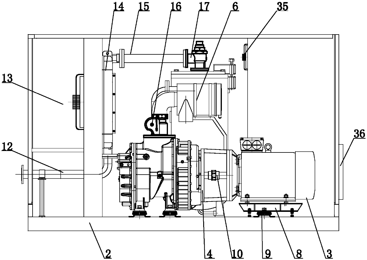
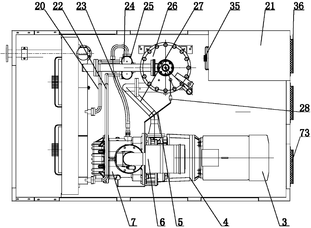
[0021] Such as Figure 25 As shown, the high-efficiency and energy-saving two-stage screw air compressor control system includes a frequency converter 69, an air compressor host 7, a motor 3, two temperature sensors, two pressure control devices, a controller 70, an oil-gas separator 26, a Heater 14, its operating steps are as follows:
[0022] (1) Start the air compressor, and the inverter starts to drive the motor;
[0023] (2) The motor drives the host to run according to the output of the frequency converter;
[0024] (3) The controller detects the status of each point of the air compressor at all times through the action of the sensor;
[0025] (4) One pressure control device detects the intermediate pressure under the primary host, and the other pressure control device detects the exhaust port pressure;
[0026] (5) One temperature sensor detects the exhaust port temperature of the primary main engine, and the other temperature sensor detects the exhaust port temperat...
Embodiment 2
[0041] Such as Figure 11 As shown, the difference between this embodiment and Embodiment 1 is that the bottom surface of the air compressor case 1 is provided with an air compressor base 58 and a motor base 60, and the air compressor base 7 is installed on the air compressor base 58 , the bottom of the motor 3 is provided with a mounting base 71, the mounting base 71 is installed on the motor base 60, the length of the motor base 60 is greater than the length of the mounting base 71, and the air compressor host 7 is installed on the air compressor base 58 by bolts , the mounting seat 71 is installed on the motor base 60 by bolts, and the installation is more convenient; in addition, the length of the motor base 60 is greater than the length of the mounting seat 71 of the motor 3, and when the motor 3 needs to be removed for maintenance or maintenance, the motor 3 can be installed in the Move on the motor base 60, the motor 3 is still shelved on the motor base 60, without havi...
Embodiment 3
[0043] Such as Figure 18As shown, the difference between this embodiment and Embodiment 1 is that the oil-gas separator 26 includes a barrel body and an oil mark 41, the upper end cover of the barrel body is provided with an upper cover A42, and the bottom of the barrel body is connected with an oil mark lower connection pipe 43, and the lower part of the barrel body The side wall is connected with an oil standard upper connection pipe 44, the oil standard upper connection pipe 44 and the oil standard lower connection pipe 43 are connected with the oil standard 41, the oil standard upper connection pipe 44 and the oil standard lower connection pipe 43 are connected with the oil standard 41 by bolt A45, the upper The edge of the cover A42 and the upper end of the staving pass through the rotating shaft A46, and the upper cover A42 and the staving are connected by a fixing bolt A47. A lower bracket A48 is arranged on the upper part of the outer side wall of the staving, and the ...
PUM
 Abstract
Description
Claims
Application Information