Laptop rotary shaft cavity and manufacturing technology thereof

A technology for notebook computers and manufacturing processes, applied in pivot connection, digital processing power distribution, etc., can solve the problems of inability to meet diverse needs, difficult to meet aesthetic requirements, large core draft angle, etc. Flawless, stable rotation, deep welding results

Inactive Publication Date: 2018-03-27
KUNSHAN WISPREN ELECTRONICS TECH CO LTD
View PDF3 Cites 5 Cited by
  • Summary
  • Abstract
  • Description
  • Claims
  • Application Information

AI Technical Summary

Problems solved by technology

[0003] At present, the rotating shaft parts used to connect the notebook computer display and keyboard body are zinc alloy integral die-casting parts. Because they are the connection keys of the notebook computer display and keyboard and are exposed, the appearance requirements are high and the colors are diverse. However, die-casting molding is very difficult. It is difficult to meet the appearance requirements: there are parting lines on the surface, and bubbles will be generated during electroplating treatment; the product cavity is deep, die-casting, and the core draft angle is large, it is difficult to meet the vertical aesthetic requirements, and the surface treatment is currently only Can be electroplated, but cannot meet diverse needs
[0004] In addition, the Chinese patent "Laptop wiring structure in the shaft compartment", application number 201310057297.0, application publication number CN 103149988 A, only discloses "including the notebook shaft compartment, and a pair of inwardly opened clamping wires are symmetrically arranged inside the shaft compartment." The door, the wire clamping door or the wire clamping door and the inner wall of the shaft compartment are used to set the wiring position", which focuses on the wiring structure of the shaft compartment, and does not solve the above problems

Method used


Image

  • Laptop rotary shaft cavity and manufacturing technology thereof
  • Laptop rotary shaft cavity and manufacturing technology thereof
  • Laptop rotary shaft cavity and manufacturing technology thereof

Examples


Embodiment

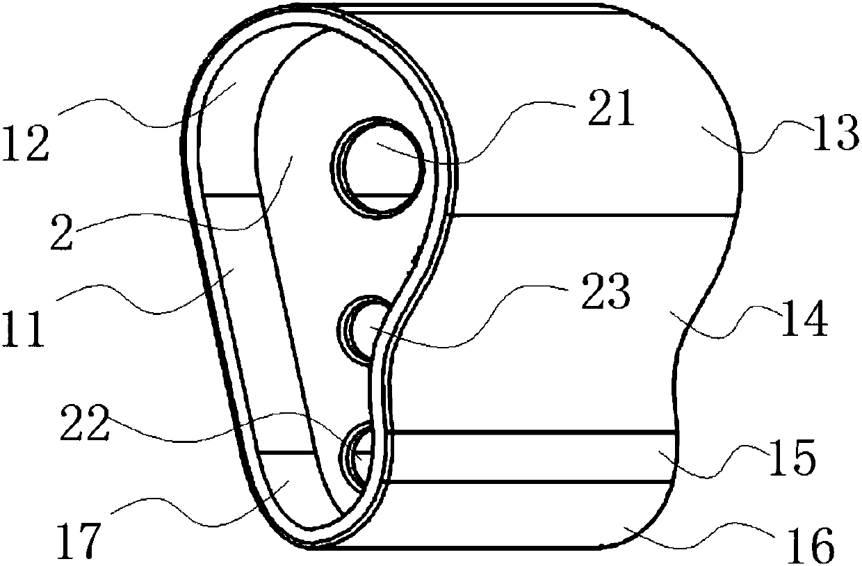
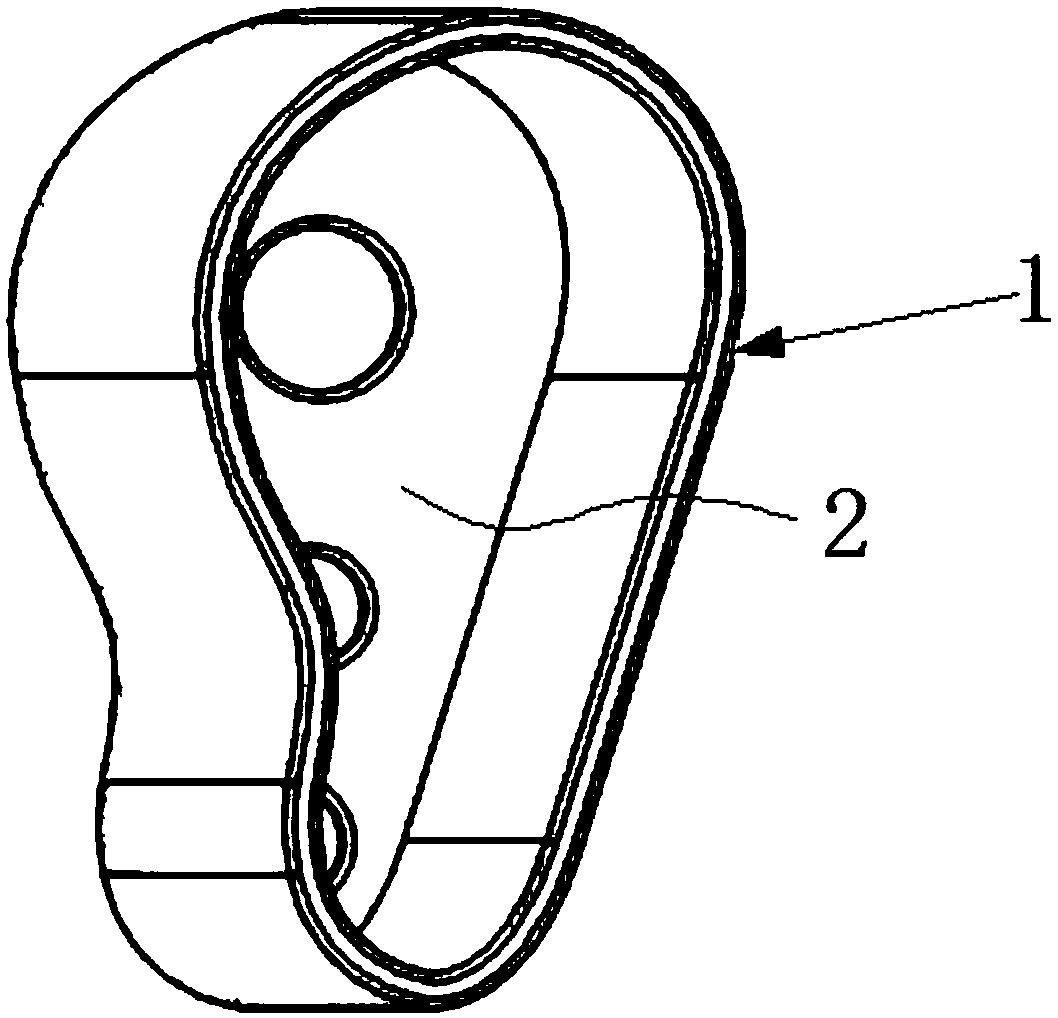
[0053] Embodiment: a kind of notebook computer shaft chamber, such as Figure 1 to Figure 6 As shown, it includes a cylindrical cavity 1 and a baffle 2 arranged in the cylindrical cavity, an accommodating space is formed in the cylindrical cavity, and the baffle is connected with the inner wall of the cylindrical cavity by spot welding And the baffle is perpendicular to the inner wall of the cylindrical cavity;

[0054] The cylindrical cavity includes seven successively connected surfaces, which are respectively a first plane 11, a first convex arc surface 12, a second convex arc surface 13, and a third arc surface first convex and then concave. 14. The fourth convex arc surface 15, the fifth convex arc surface 16 and the sixth arc surface 17 are convex, the seven surfaces are integrally formed, and the first plane is opposite to the second arc surface , the first arc surface, the second arc surface, the third arc surface, the fourth arc surface, the fifth arc surface and the...


PUM

PropertyMeasurementUnit
lengthaaaaaaaaaa
widthaaaaaaaaaa
heightaaaaaaaaaa

Abstract

The invention discloses a laptop rotary shaft cavity and a manufacturing technology thereof. The rotary shaft cavity comprises a cylindrical cavity body and a blocking piece arranged in the cylindrical cavity body. An accommodating space is formed in the cylindrical cavity body. The blocking piece and the inner wall of the cylindrical cavity body are in spot welding connection, and the blocking piece is perpendicular to the inner wall of the cylindrical cavity body. The blocking piece is welded to the inner wall of the cylindrical cavity body by adopting laser spot welding. The rotary shaft cavity provided by the invention is simple in structure, attractive in appearance, convenient to process and form, and high in rate of matching with a rotary shaft of a laptop; after mounting, the rotary shaft is not prone to loosening, the matching rate is high, rotation is stable, and the service life of the product is long; and the blocking piece and the cylindrical cavity body are connected through laser spot welding, no residue exists, the connecting position is flawless, and the laptop rotary shaft cavity and the manufacturing technology thereof are suitable for high-end laptop products.

Description

technical field [0001] The invention belongs to the technical field of notebook computer hinges, and in particular relates to a notebook computer hinge cavity and a manufacturing process thereof. Background technique [0002] With the development of science and technology, various electronic products continue to appear, which bring great changes to people's lives, especially the use of computers has changed people's lifestyles and accelerated their pace of life. In the past two decades, with the development of material science and the emergence of smaller integrated chips, computers have evolved into a notebook computer that is small in size, thin in thickness, light in weight and easy to carry around. Most of the existing notebooks are of flip-top type. In order to meet the design considerations of thinness, smallness and light weight, they are generally designed to be composed of two parts: the base composed of the host body and the keyboard, and the upper cover composed o...

Claims


Application Information

Patent Timeline
Patent Type & Authority Applications(China)
IPC IPC(8): F16C11/04G06F1/18B23P15/00
CPCF16C11/04B23P15/00G06F1/18
Inventor 吴红兵
Owner KUNSHAN WISPREN ELECTRONICS TECH CO LTD
Why Eureka
Try Eureka