Energy-saving and environment-friendly drying device

A drying device, energy saving and environmental protection technology, applied in drying, drying machine, drying solid materials, etc., can solve the problems of inconvenient material discharge, slow drying speed, large drying load, etc., to improve heat dissipation efficiency and Heat dissipation speed, convenient discharge, and the effect of improving heating efficiency

Pending Publication Date: 2018-03-27
黄冬梅
View PDF6 Cites 4 Cited by
  • Summary
  • Abstract
  • Description
  • Claims
  • Application Information

AI Technical Summary

Problems solved by technology

[0003] However, during the drying process of the materials in the existing material drying device, the materials are accumulated in the drying bucket, resulting in an excessive drying load of the materials, which needs to absorb a large amount of heat, and the drying speed of the materials is slow, which brings great inconvenience to people. The use causes certain inconvenience, and the existing drying device often blocks the discharge pipe after the material is dried, which brings certain inconvenience to the discharge work of the material, and the practicability is poor.

Method used


Image

  • Energy-saving and environment-friendly drying device
  • Energy-saving and environment-friendly drying device
  • Energy-saving and environment-friendly drying device

Examples


Embodiment 1

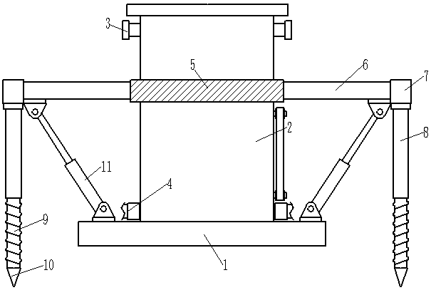
[0028] Such as figure 1 As shown, an energy-saving and environment-friendly drying device includes a drying barrel 2, the bottom of the drying barrel 2 is fixedly connected with a shock-absorbing base 1, and the drying barrel 2 is provided with a feed pipe 3 and a row Material pipe 4, and described feed pipe 3 and discharge pipe 4 are provided with valve, and described drying barrel 2 side walls are fixedly connected with fixing plate 5, and fixing plate 5 is connected with described drying barrel 2 fixed welding, and the fixed plate 5 runs through the drying barrel 2, the fixed plate 5 is a hollow structure with openings at both ends, and the fixed plate 5 is provided with an opening and closing plate 6, the opening and closing plate The two ends of 6 respectively extend to the outside of the fixed plate 5, the end of the opening and closing plate 6 is fixedly connected to the limit block 7, and the bottom of the limit block 7 is fixedly connected to the fixed cylinder 8, the...

Embodiment 2

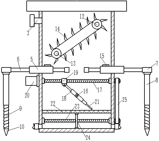
[0033] Such as figure 1 As shown, an energy-saving and environment-friendly drying device, on the basis of Embodiment 1, the inner bottom of the drying barrel 2 is fixedly connected with a fixed bottom plate 22, and a through hole is arranged above the fixed bottom plate 22, and the described drying The inner bottom of the barrel 2 is provided with a rotating shaft 23, one end of the rotating shaft 23 is rotatably connected to the inner wall of the drying barrel 2, and the other end of the rotating shaft 23 is rotatably connected to the drying barrel 2 and extends to the drying Outside the barrel 2, the rotating shaft 17 extends to the outside of the drying barrel 2 and is rotationally connected with the drying barrel 2, and the rotating shaft 17 is connected to the rotating shaft 23 through a transmission belt 25; the rotating Threads are evenly distributed on the surface of the shaft 23 , and a reciprocating plate 24 is sheathed on the rotating shaft 23 , and the reciprocati...

Embodiment 3

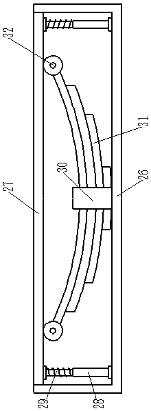
[0036] Such as figure 1 and image 3 As shown, an energy-saving and environment-friendly drying device, on the basis of Embodiment 1, the shock-absorbing base 1 is mainly composed of a fixed frame 26 and a sliding plate 27, and the sliding plate 27 and the fixed frame 26 Slidingly connected, the sliding plate 27 is fixedly connected with the drying barrel 2, the inner bottom of the fixed frame 26 is fixedly connected with a U-shaped clamp 30, and the U-shaped clamp 30 is fixedly connected with a shock-absorbing steel plate 31, and the shock-absorbing The end of the steel plate 31 is connected with a shock-absorbing roller 32, and the shock-absorbing roller 32 is connected with the sliding plate 27, and the inner bottom of the fixed frame 26 is symmetrically fixedly connected with fixed columns 28 on both sides, and the fixed columns 28 are open at the top. The hollow structure of the fixed column 28 is slidingly connected with a sliding rod 29, the top of the sliding rod 29 i...


PUM


Abstract

The invention discloses an energy-saving and environment-friendly drying device. The energy-saving and environment-friendly drying device comprises a drying barrel; the bottom of the drying barrel isfixedly connected with a damping base; the side wall of the drying barrel is fixedly connected with a fixing plate; the fixing plate is fixedly welded to the drying barrel; the fixing plate penetratesthrough the drying barrel; an opening and closing plate is arranged in the fixing plate; two ends of the opening and closing plate separately extend to the outer sides of the fixing plate; the tail ends of the opening and closing plate are fixedly connected with limiting blocks; the bottom of each limiting block is fixedly connected with a fixed barrel; a threaded rod is connected into each fixedbarrel through threads; the bottom of each threaded rod is integrally and fixedly connected with a stabilization tooth; a driving wheel and a driven wheel are arranged in the drying barrel and are connected through a transmission chain; multiple material overturning hoppers; the drying wheel is connected with the power output end of a motor on the outer side; and a heater is fixedly connected tothe surface of the fixing plate and is electrically connected to a power source on the outer side. The device has the advantages that material drying efficiency is high; clogging caused by materials cannot happen; damping performance and stability are high; and practicability is high.

Description

technical field [0001] The invention belongs to the field of drying, and in particular relates to an energy-saving and environment-friendly drying device. Background technique [0002] The drying device is one of the indispensable devices in the production and processing of materials. The drying device is mainly a kind of equipment that heats the materials through the heater, thereby causing the materials to dry, which provides a greater guarantee for people's work and life. Convenience, welcomed by people. [0003] However, during the drying process of the materials in the existing material drying device, the materials are accumulated in the drying bucket, resulting in an excessive drying load of the materials, which needs to absorb a large amount of heat, and the drying speed of the materials is slow, which brings great inconvenience to people. The use causes certain inconvenience, and the existing drying device often blocks the discharge pipe after the material is dried,...

Claims


Application Information

Patent Timeline
Patent Type & Authority Applications(China)
IPC IPC(8): F26B11/12F26B25/00F26B25/04
CPCF26B11/12F26B25/00F26B25/001F26B25/04
Inventor 黄冬梅
Owner 黄冬梅
Why Eureka
Try Eureka