
Apparatus and method for combined testing of gas content andC1-C15 light hydrocarbon components of rock.

A C1-C15, combined testing technology, applied in the field of oil and gas exploration and development, can solve the problems of low work efficiency, desorption and loss of gas substances, harsh environment and experimental technology requirements, etc., to improve work efficiency, easy operation, overcome non- Effect of Homogeneity and Ambient Temperature Influence

Active Publication Date: 2018-03-27
CHINA PETROLEUM & CHEM CORP +1
View PDF11 Cites 3 Cited by
  • Summary
  • Abstract
  • Description
  • Claims
  • Application Information

AI Technical Summary

Problems solved by technology

The main problem of these methods is that the coarse crushing process and the fine crushing process are completed in two different systems, the coarse crushing process of large core samples is carried out in the open system, and the coarse crushing process and the sample transfer to the closed fine crushing system process There is desorption and loss of gas substances in rocks, and the amount of loss cannot be measured, which will inevitably lead to low gas content results in the final rock, which cannot accurately reflect the real gas content in rock samples
To the test of rock light hydrocarbon, the method used at present mainly adopts the method (CN02160133.X; ZL200310103219.6; Jiang Qigui, 2004; Jiang Qigui, 2007; Etc.) of rock sealing broken low-boiling point Freon solvent extraction, this method needs the Freon solvent Carry out rectification and purification, and at the same time, the experiment process should be carried out at low temperature (below 18°C), the experiment process is complicated, the environment and experiment technology are strict, and only C6-C15 light hydrocarbon components can be tested
Rock gas content and rock light hydrocarbon analysis are separately sampled and tested separately, which has the problem of sample heterogeneity and low work efficiency

Method used


Image

  • Apparatus and method for combined testing of gas content andC1-C15 light hydrocarbon components of rock.

Examples


Embodiment Construction

[0036] The present invention will be further described below in conjunction with accompanying drawing.

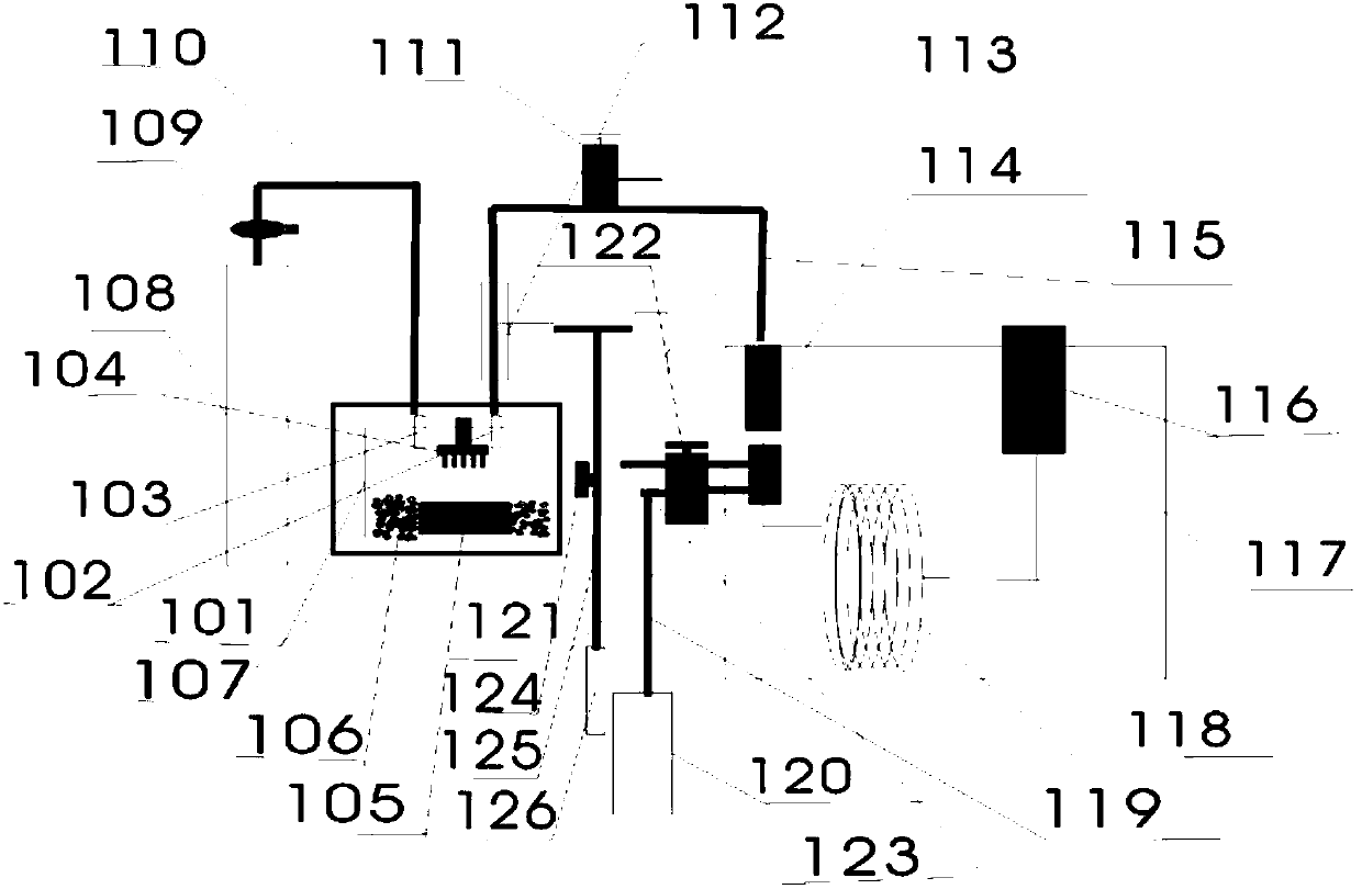
[0037] figure 1 It is a schematic diagram of the device for joint testing of rock gas content and C1-C15 light hydrocarbon components. Including sealed sample broken sample degassing system and online light hydrocarbon analysis system (not indicated in the figure).

[0038] The sealed broken sample degassing system includes a sealed broken sample tank 101 and a heating box 107 set on the sealed broken sample tank 101; the online light hydrocarbon analysis system includes a chromatographic box 117, which is arranged on the top side of the chromatographic box 117 vaporization chamber 114, the detector 116 arranged on the other side of the chromatographic case 117 top, the smart cold trap 121 arranged inside the chromatographic case, the front end of the chromatographic column 118 passes through the smart cold trap 121 and is connected with the vaporization chamber 114, so T...


PUM


Abstract

The invention relates to an apparatus and a method for combined testing of the gas content and the C1-C15 light hydrocarbon components of rock. The apparatus comprises a sealed sample breaking tank, aheating box, a chromatography box, a vaporization chamber, a detector, an intelligent cold trap, a chromatography column and a vaporization chamber, wherein a helium gas inlet pipeline and a helium gas outlet pipeline respectively pass through both sides on the top portion of the heating box, one end of the helium gas inlet pipeline on one side is connected to a helium gas bottle, the other end is connected to the first gas valve of the sample breaking tank, one end of the helium gas outlet pipeline on the other side is connected to the vaporization chamber, and the other end is connected tothe second gas valve of the sample breaking tank. According to the present invention, the operation is convenient, the solvent is not used, the working efficiency is improved, and the problems of thenon-uniformity of the sample and the influence caused by the ambient temperature can be overcome.

Description

technical field [0001] The technical field of the invention is oil and gas exploration and development, and relates to a testing device for gaseous hydrocarbons and light hydrocarbons in rocks, processing of rock samples and preparation and analysis of hydrocarbon substances. Background technique [0002] In the field of oil and gas exploration and development research, it is necessary to analyze and test the gas content and light hydrocarbon components of drilling core samples or geological section rock samples. Although there are many methods for testing rock gas content and rock light hydrocarbons, there are There is no such or that problem, and there is no device that can realize the joint test of rock gas content and light hydrocarbon components. For the test of rock gas content, the widely used method is to coarsely crush the massive core sample into smaller particle samples in an open system, and then carry out closed and fine crushing of small particle samples into p...

Claims


Application Information

Patent Timeline
IPC IPC(8): G01N30/00
CPCG01N30/00
Inventor 蒋启贵腾格尔李志明申宝剑钱门辉黎茂稳
Owner CHINA PETROLEUM & CHEM CORP
Features
  • Generate Ideas
  • Intellectual Property
  • Life Sciences
  • Materials
  • Tech Scout
  • Unparalleled Data Quality
  • Higher Quality Content
  • 60% Fewer Hallucinations
Learn More