Two-dimensional magnetic circuit modeling method of single-phase cylindrical linear switched reluctance motor

A switched reluctance, linear motor technology, applied in electrical digital data processing, special data processing applications, instruments, etc., can solve the problems of complex mathematical analysis models, large calculation and storage space, and highly nonlinear models.

Active Publication Date: 2018-03-27
CHINA UNIV OF MINING & TECH
View PDF3 Cites 3 Cited by
  • Summary
  • Abstract
  • Description
  • Claims
  • Application Information

AI Technical Summary

Problems solved by technology

However, due to the double salient pole structure and magnetic saturation characteristics of the cylindrical switched reluctance linear motor, the model is highly nonlinear and the mathematical analysis model is complicated.
At present, the magnetic characteristics of the cylindrical switched reluctance linear motor are mainly calculated by using the motor electromagnetic field finite element method to calculate the magnetization characteristics of the cylindrical switched reluctance linear motor, and the two-dimensional finite element electromagnetic field calculation is difficult to fully reveal the cylindrical switched reluctance linear motor. The magnetic characteristics of the motor often require a three-dimensional finite element electromagnetic

Method used


Image

  • Two-dimensional magnetic circuit modeling method of single-phase cylindrical linear switched reluctance motor
  • Two-dimensional magnetic circuit modeling method of single-phase cylindrical linear switched reluctance motor
  • Two-dimensional magnetic circuit modeling method of single-phase cylindrical linear switched reluctance motor

Examples


Embodiment Construction

[0068] An embodiment of the present invention will be further described below in conjunction with the accompanying drawings:

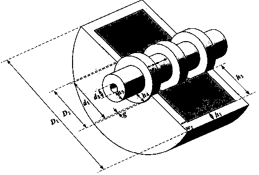
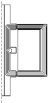
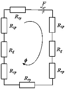
[0069] The present invention takes a single-phase cylindrical switched reluctance linear motor as an example, and the resulting size diagram is as follows figure 1 Shown. According to the distribution of magnetic lines of force at different positions of the single-phase cylindrical switched reluctance linear motor, the distribution of magnetic lines of force at the aligned positions is as follows figure 2 As shown, the equivalent magnetic circuit model of the single-phase cylindrical switched reluctance linear motor is obtained as image 3 Shown.

[0070] At mover position x u Where, the air gap reluctance part can be divided into R g1 , R g2 And R g3 Three parts, the partition of the air gap reluctance part is as Figure 4 Shown. Air gap reluctance component R g1 Yes

[0071]

[0072] Where h 2 , H 3 And h 4 They are the stator slot depth, mover yoke thic...


PUM


Abstract

The invention discloses a two-dimensional magnetic circuit modeling method of a single-phase cylindrical linear switched reluctance motor. All calculation formulas of each reluctance component in fivemagnetic circuits combine to form the magnetic circuit model of the single-phase cylindrical linear switched reluctance motor, wherein the five magnetic circuits include the rotor position x wherethe central line of a rotor groove is aligned with that of a stator tooth of the cylindrical linear switched reluctance motor, the rotor position w<4>/4 where the overlapping part of a rotor tooth and the stator tooth occupies a quarter of the width of the stator tooth, the rotor position w<4>/2 where the overlapping part of the rotor tooth and the stator tooth occupies a half of the width of thestator tooth, the rotor position 3*w<4>/4 where the overlapping part of the rotor tooth and the stator tooth occupies three quarters of the width of the stator tooth and the rotor position where thecentral line of the rotor tooth is aligned with that of the stator tooth; it is unnecessary to adopt a motor electromagnetic field finite element method to calculate the magnetic property of the motor, calculation is fast, rapid design, real-time simulation and real-time control of the single-phase cylindrical linear switched reluctance motor system can be achieved, and the method has good engineering application value.

Description

Technical field [0001] The invention relates to a two-dimensional magnetic circuit modeling method of a single-phase cylindrical switched reluctance linear motor, in particular to a two-dimensional magnetic circuit modeling method of a switched reluctance motor. Background technique [0002] The switched reluctance linear motor has the advantages of simple structure, strong fault tolerance, high reliability, and simple control. It can also directly convert electrical energy into mechanical energy for linear motion without an intermediate mechanical conversion mechanism, which improves energy conversion efficiency. The large normal force caused by the inherent structure of the traditional unilateral switched reluctance linear motor causes a large friction force between the mover and the track and shortens the service life of the motor. The double-sided switched reluctance linear motor can alleviate this problem by virtue of its symmetrical stator structure, but as long as there is...

Claims


Application Information

Patent Timeline
IPC IPC(8): G06F17/50
CPCG06F30/17G06F30/20
Inventor 陈昊闫文举李志雄
Owner CHINA UNIV OF MINING & TECH
Why Eureka
Try Eureka