
Method and apparatus in grant free UE (User Equipment) and base station

A first, target resource technology, applied in the direction of network traffic/resource management, electrical components, wireless communication, etc., can solve problems such as inability to receive correctly

Active Publication Date: 2018-03-27
SHANGHAI LANGBO COMM TECH CO LTD
View PDF3 Cites 10 Cited by
  • Summary
  • Abstract
  • Description
  • Claims
  • Application Information

AI Technical Summary

Problems solved by technology

[0004] The inventors have discovered through research that under autonomous / grant free / competition-based non-orthogonal multiple access, it is necessary to study a mechanism to ensure the transmission quality of important data, such as physical layer signaling and Services with high real-time requirements, and solve the problem that the same data cannot be received correctly after multiple retransmissions

Method used


Image

  • Method and apparatus in grant free UE (User Equipment) and base station
  • Method and apparatus in grant free UE (User Equipment) and base station
  • Method and apparatus in grant free UE (User Equipment) and base station

Examples


Embodiment 1

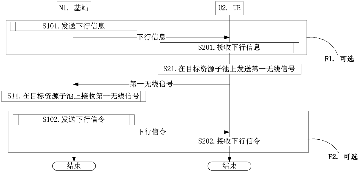
[0145] Embodiment 1 illustrates the flow chart of wireless transmission, as attached figure 1 shown. attached figure 1 In , the base station N1 is the serving cell maintenance base station of the UE U2. attached figure 1 , the steps in Box F1 and Box F2 are optional, respectively.

[0146] For N1, send downlink information in step S101; receive the first wireless signal on the target resource subpool in step S11; send downlink signaling in step S102.

[0147] For U2, receive downlink information in step S201; send a first wireless signal on the target resource subpool in step S21; receive downlink signaling in step S202.

[0148] In Embodiment 1, the UE U2 determines the target resource pool according to at least one of {the first parameter, the second parameter}, and the base station N1 determines {the first parameter, the second parameter} according to the target resource pool } at least one of the The target resource pool is a candidate resource pool among G candidate ...

Embodiment 2

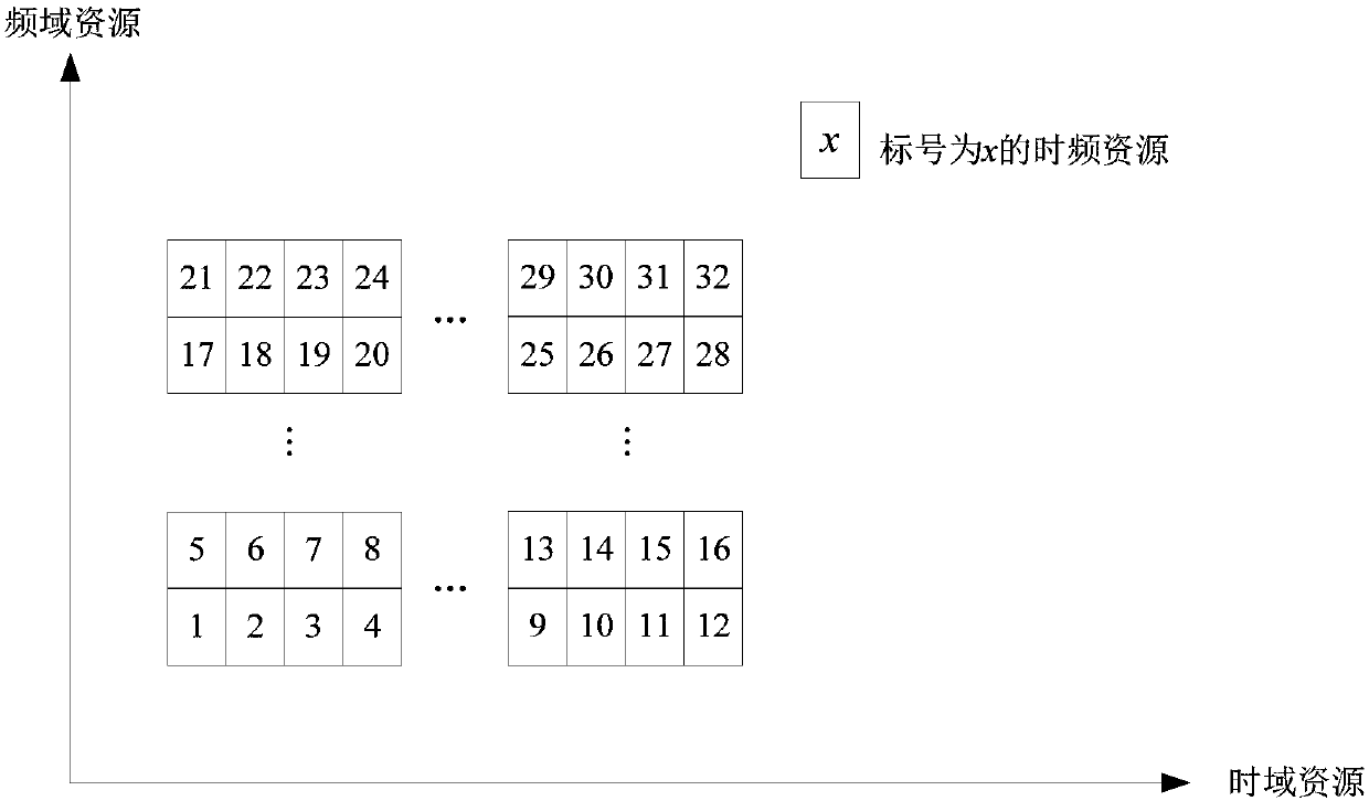
[0169] Embodiment 2 illustrates a schematic diagram of resource mapping of G candidate resource pools in the time-frequency domain in the present invention, as shown in the attached figure 2 shown.

[0170] In Embodiment 2, the first resource pool and the second resource pool are any two different candidate resource pools among the G candidate resource pools, wherein the first resource pool includes K1 time-frequency resources, the second resource pool includes K2 time-frequency resources, and the K1 is smaller than the K2. in the attached figure 2 In , a square with a numerical label represents a time-frequency resource, and the time-frequency resources with different labels are distributed continuously or discontinuously in the time-frequency domain, as shown in the appended figure 2 shown.

[0171] As a sub-embodiment 1 of Embodiment 2, one time-frequency resource includes P time-frequency sub-resources, and each time-frequency sub-resource includes Q RUs (Resource Un...

Embodiment 3

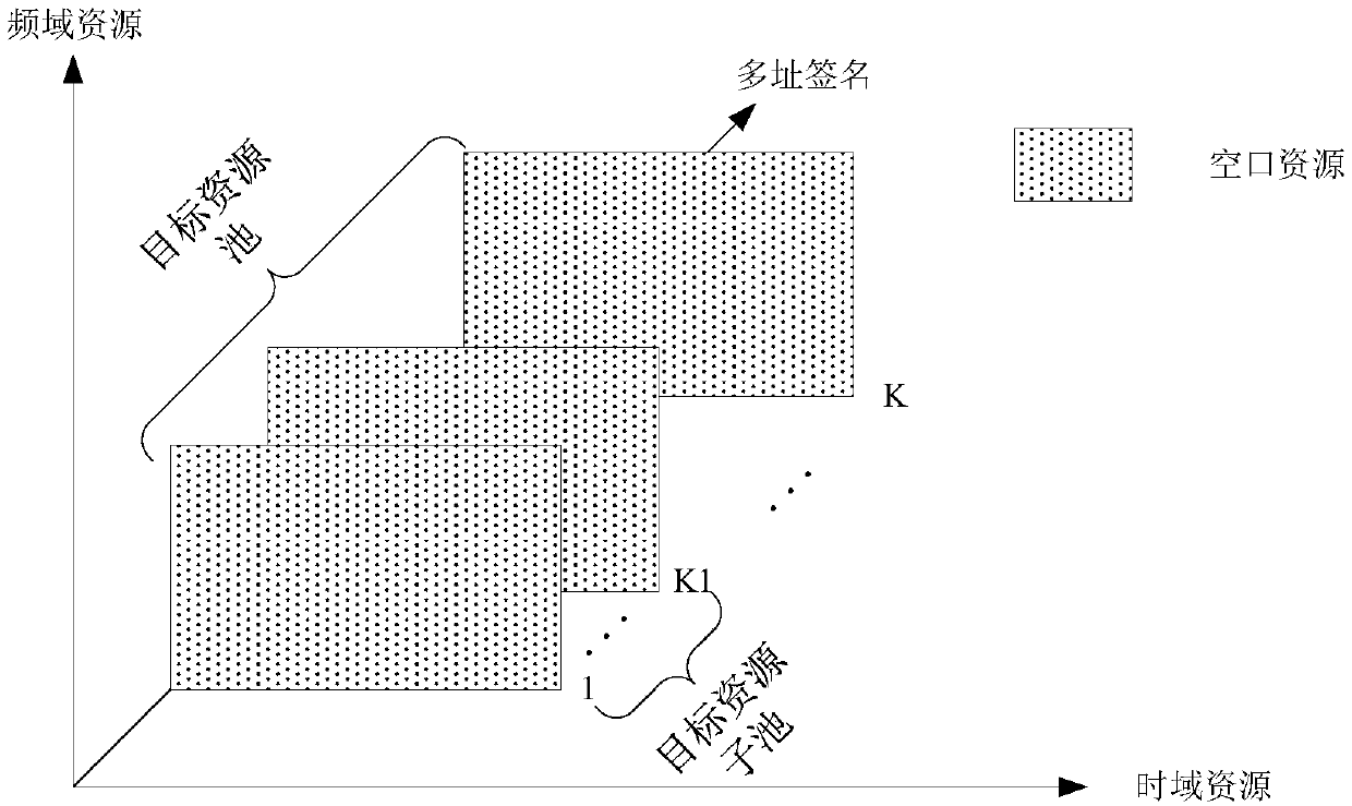
[0189] Embodiment 3 illustrates a schematic diagram of resource mapping between air interface resources and target resource subpools on the target resource pool in the present invention, as shown in the attached image 3 shown.

[0190] in the attached image 3 In , a box filled with dots represents one air interface resource. In Embodiment 3, the target resource pool includes K air interface resources, where K is a positive integer. One air interface resource includes one time-frequency resource and one multiple access signature. The target resource subpool belongs to the target resource pool, and the target resource subpool includes a positive integer number of the air interface resources.

[0191] As a sub-embodiment 1 of embodiment 3, the multiple access signature (Multiple Access Signature) includes {sequence, codebook (Codebook) / codeword (Codeword), interleaving or mapping pattern (pattern), demodulation reference signal (Demodulation reference signal), preamble (Pre...


PUM


Abstract

The invention discloses a method and an apparatus in grant free UE (User Equipment) and base station. The method comprises the following steps: determining, by a UE, a target resource pool according to at least one of {a first parameter and a second parameter}; and sending a first wireless signal on a target resource subpool, wherein the target resource pool is one of G candidate resource pools, the G is a positive integer greater than 1, the candidate resource pools include a positive integer of air interface resources, the target resource subpool belongs to the target resource pool, the target resource pool includes K air interface resources and the K is the positive integer, a first bit block is used for generating the first wireless signal, the numbers of the air interface resources included in any two candidate resource pools of the G candidate resource pools are not equal, the first parameter includes at least one of {a type of physical layer information and a business type}, thesecond parameter refers to a frequency that the first bit clock is sent until the first wireless signal, and one of the air interface resources includes a time frequency resource and a multiple access signature.

Description

technical field [0001] The present invention relates to a wireless signal transmission scheme in a wireless communication system, in particular to a method and device for uplink transmission based on cellular network communication. Background technique [0002] In a traditional digital modulation based wireless communication system, such as a 3GPP (3rd Generation Partner Project, 3rd Generation Partnership Project) cellular system, uplink wireless signal transmission is based on base station scheduling. According to the conclusion of the 3GPP RAN1 (Radio Access Network, radio access network) #84bis meeting, the next generation wireless communication system will study the non-orthogonal multiple access method based on autonomous / grant free / competitive Applications in various NR (NewRadio, new radio communication) application scenarios. At least for uplink mMTC (massive Machine-Type Communications, large-scale machine-type communication), non-orthogonal multiple access based ...

Claims


Application Information

Patent Timeline
Patent Type & Authority Applications(China)
IPC IPC(8): H04W28/04H04W72/04
CPCH04W72/0446H04W72/0453H04W72/23
Inventor 张晓博
Owner SHANGHAI LANGBO COMM TECH CO LTD
Learn More