Route generator, route generation method, and route generation program

A technology of path generation and generation department, which is applied in the directions of measuring devices, control devices, transportation and packaging, etc., which can solve the problems of heavy computing load and various computing parameters, and achieve the effect of reducing the burden

Active Publication Date: 2018-03-27
HONDA MOTOR CO LTD
View PDF12 Cites 7 Cited by
  • Summary
  • Abstract
  • Description
  • Claims
  • Application Information

AI Technical Summary

Problems solved by technology

[0010] However, in the conventional technology, when calculating the trajectory for a curved road, there are many calculation parameters, and the calculation load may become too large.

Method used


Image

  • Route generator, route generation method, and route generation program
  • Route generator, route generation method, and route generation program
  • Route generator, route generation method, and route generation program

Examples


no. 1 approach

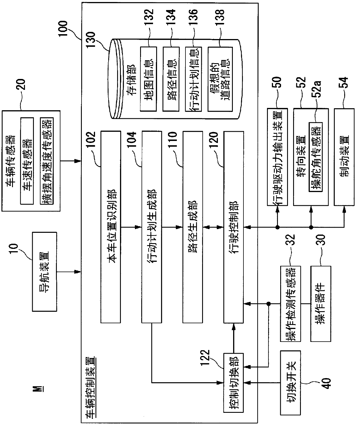
[0053] figure 1 It is a functional configuration diagram of the host vehicle M centered on the vehicle control device 100 of the first embodiment. The own vehicle M refers to a vehicle on which the vehicle control device 100 is mounted. The vehicle M is equipped with a navigation device 10 , a vehicle sensor 20 , an operating device 30 , an operation detection sensor 32 , a switch 40 , a driving force output device 50 , a steering device 52 , a braking device 54 , and a vehicle control device 100 .

[0054] The navigation device 10 includes a GNSS (Global Navigation Satellite System) receiver, map information (navigation map), a touch-panel display device functioning as a user interface, a speaker, a microphone, and the like. The navigation device 10 specifies the position of the host vehicle M using a GNSS receiver, and derives a route from the position to a destination designated by the user. The route derived by the navigation device 10 is defined by a combination of link...

no. 2 approach

[0121] Hereinafter, a second embodiment will be described. The vehicle control device 100A in the second embodiment is different from the first embodiment in that, when there is an object that hinders the running of the own vehicle M, the own vehicle M is controlled under constraints corresponding to the curvature of the road. drive. The following description will focus on such differences.

[0122] Figure 12 It is a diagram showing components of a host vehicle M equipped with a vehicle control device 100A according to the second embodiment. Such as Figure 12As shown, the host vehicle M is equipped with a navigation device 10 , sensors 60 - 1 to 60 - 7 , radars 70 - 1 to 70 - 6 , sensors such as a camera 80 , and a vehicle control device 100A.

[0123] The detectors 60 - 1 to 60 - 7 are, for example, LIDAR (Light Detection and Ranging, or Laser Imaging Detection and Ranging) that measure the distance to the object with respect to scattered light of the irradiated light. ...

no. 3 approach

[0175] Hereinafter, a third embodiment will be described. The vehicle control device 100B of the third embodiment differs from the first and second embodiments in that, when an obstacle OB exists on the road, the generated trajectory Tg# is considered to be a virtual transformation of its shape. The size of the obstacle OB. The following description will focus on such differences.

[0176] The conversion unit 112 of the third embodiment converts the shape of the road into a straight line when the outside world recognition unit 103 recognizes an obstacle OB on the own lane, and converts the shape of the obstacle OB on the road into a straight line. convert. For example, the shape of the obstacle OB is the above Figure 15 In the case of a circle as shown, the shape of the road is transformed into a linear shape, and the side close to the reference point P is converted to expand in the X direction, which is the traveling direction of the vehicle, and the side farther from the...


PUM


Abstract

A route generator is provided with: a conversion unit for generating, on the basis of map information including information that indicates the road shape, virtual road information in which the road shape is converted to a linear shape; a travel path generation unit for generating a path over which a host vehicle travels on the linear road in the virtual road information generated by the conversionunit; and an inverse conversion unit for performing, on the travel path of the host vehicle generated on the linear road by the travel path generation unit, an inverse conversion of the conversion performed by the conversion unit, thereby generating the travel path of the host vehicle on the road shape prior to being converted to a linear shape by the conversion unit.

Description

technical field [0001] The present invention relates to a route generating device, a route generating method, and a route generating program. [0002] This application claims priority based on Japanese Patent Application No. 2015-144994 filed on July 22, 2015 and Japanese Patent Application No. 2016-051076 filed on March 15, 2016, the contents of which are incorporated herein by reference . Background technique [0003] Conventionally, there is known a technique for controlling the travel of a vehicle according to a preset travel trajectory on a road such as a curved road. In connection with this, there is known a vehicle running track setting device that detects a dividing line indicating a lane in front of the vehicle with an imaging device, and sets a running track of the vehicle based on the dividing line. The setting device is characterized in that it includes: a position detection mechanism that detects the position of the inner peripheral side dividing line at a pos...

Claims


Application Information

Patent Timeline
Patent Type & Authority Applications(China)
IPC IPC(8): G08G1/16G01C21/26B62D6/00B62D101/00B62D137/00
CPCB60W30/08B60W30/095B60W30/12B60W30/14G08G1/167B60W2050/065G01C21/3629G01C21/3658G01C21/12G01C21/30G01C21/3446B60W2554/80B60W2552/30B60W2554/00B60W2556/50B60W2554/4029B60W2552/53B60W2554/406B60W2552/05B60W60/0011B60W60/0053B60W2554/20B60W2554/4045G01C21/3415G01C21/3602G01C21/3676G01C21/3694G05D2201/0213G08G1/16
Inventor 武田政宣
Owner HONDA MOTOR CO LTD
Why Eureka
Try Eureka