Automatic construction rebar bending mechanism

A technology of bending mechanism and building steel bar, which is applied in the field of building material processing equipment, can solve the problems of steel bar bending machine such as single function, low work efficiency, and affecting processing efficiency, so as to shorten the assembly line and processing time, improve work efficiency, and have a simple structure Effect

Inactive Publication Date: 2018-03-30
郑州众益德网络科技有限公司
View PDF0 Cites 2 Cited by
  • Summary
  • Abstract
  • Description
  • Claims
  • Application Information

AI Technical Summary

Problems solved by technology

[0003] The existing CNC steel bar bending machine can realize the cutting and bending steps of the steel bar. However, when the existing steel bar bending machine cuts or bends the steel bar, the feeding device must stop and wait for the steel bar to be cut or bent. , the material can be fed again, because the feeding device must stop when cutting or bending the steel bar, which affects the proce

Method used


Image

  • Automatic construction rebar bending mechanism
  • Automatic construction rebar bending mechanism
  • Automatic construction rebar bending mechanism

Examples


Example Embodiment

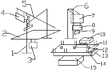
[0028] Embodiment 2: The feeding and pushing assembly 4 includes a feeding and pushing power element, a feeding chute and a feeding push block matched with the feeding slide rail 5; the fixed end of the feeding and pushing power element is fixedly connected with one end of the feeding slide rail 5, and the feeding and pushing power element The working end of the feeding chute is slidably connected with the lower wall of the feeding slide rail 5 through the upper wall of the feeding chute, and the lower end of the feeding chute is fixedly connected with the feeding push block; further, the feeding and pushing power element can be a standard cylinder pneumatic element; 3. After the silo 2 is raised to a certain height, the feeding and pushing power element works, that is, the telescopic rod in the feeding and pushing power element is extended, and the reinforcing material in the silo 2 is pushed to the material plate 11 by the feeding push block.

[0029] Preferably, the bending ...


PUM


Abstract

The invention provides an automatic bending mechanism for building steel bars, which includes a feeding device, a cutting device, a steel bar bending device, and a receiving bin arranged on the front side of the steel bar bending device; the steel bar bending device includes a Feeding device, the bending device on the right side of the feeding device; the feeding device includes a gantry, a silo, a feeding lifting component, and a feeding pushing component; the bending device includes a bending frame, a bending component, and a bending component for matching Auxiliary parts for bending steel bars; auxiliary parts include a material plate, a plurality of bending parts, a discharge power assembly arranged on the side of the material plate and a horizontal moving assembly for adjusting the position of the material plate; the invention has a simple structure , other processes can continue to work when the steel bar is bent; multiple automatic bending of the steel bar material can be realized, and the bending angle of the steel bar material can be adjusted at any time; the bent steel bar material is pushed to the receiving bin through the discharging power component , shorten the processing time and improve work efficiency.

Description

technical field [0001] The invention relates to the field of building material processing equipment, in particular to an automatic bending mechanism for building steel bars. Background technique [0002] A large number of steel bars and stirrups processed from steel bars are widely used in modern construction projects. Steel bars are usually stored and transported in the form of coils. Before use, they must be straightened, cut to length, and some of them need to be bent. processing steps; [0003] The existing CNC steel bar bending machine can realize the cutting and bending steps of the steel bar. However, when the existing steel bar bending machine cuts or bends the steel bar, the feeding device must stop and wait for the steel bar to be cut or bent. , the material can be fed again, because the feeding device must stop when cutting or bending the steel bar, which affects the processing efficiency; and the existing steel bar bending machine has too single function to real...

Claims


Application Information

Patent Timeline
IPC IPC(8): B21F1/00B21F23/00
CPCB21F1/004B21F23/00
Inventor 林丽娟
Owner 郑州众益德网络科技有限公司
Why Eureka
Try Eureka