Control method of air cooling screw heat pump system

A technology of heat pump system and air-cooled screw, which is applied in refrigerators, refrigeration components, refrigeration and liquefaction, etc., and can solve the problems of complex operation and single operation

Inactive Publication Date: 2018-03-30
WUXI VOCATIONAL & TECHN COLLEGE
View PDF3 Cites 0 Cited by
  • Summary
  • Abstract
  • Description
  • Claims
  • Application Information

AI Technical Summary

Problems solved by technology

[0004] However, the operation for this kind of air-cooled screw heat pump system is often relatively simple and complicated.

Method used


Image

  • Control method of air cooling screw heat pump system
  • Control method of air cooling screw heat pump system
  • Control method of air cooling screw heat pump system

Examples


Embodiment 1

[0021] Embodiment 1: A control method for an air-cooled screw heat pump system:

[0022]

[0023]

[0024]

[0025]

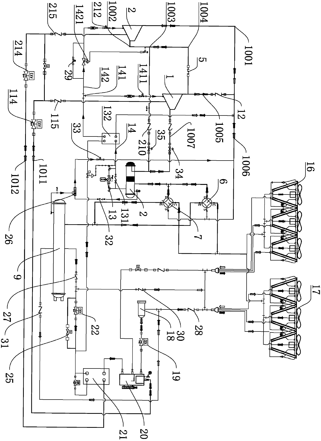
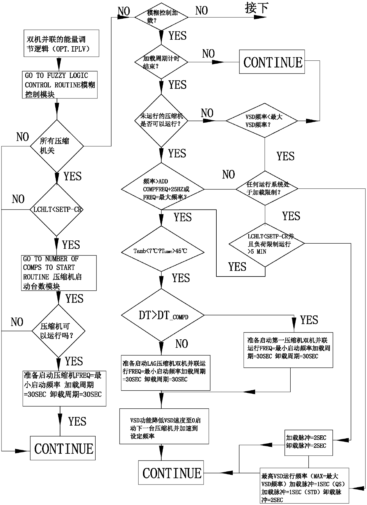
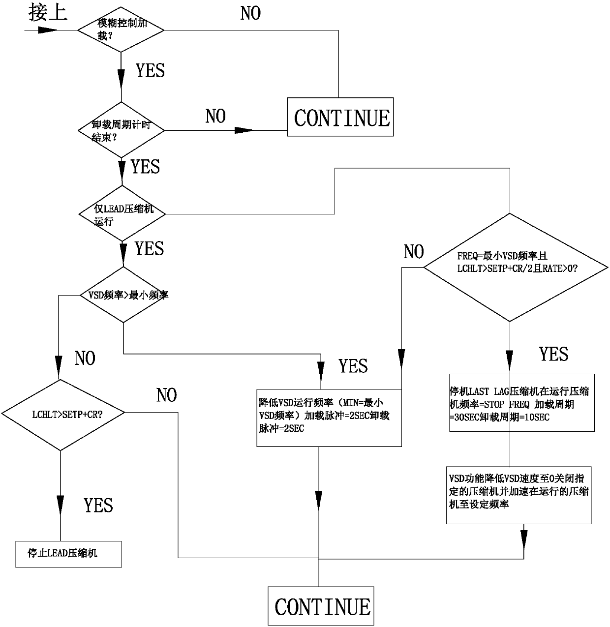
[0026] The key to two-stage compression control is how to effectively control the intermediate pressure, that is, to reasonably match and control the load percentage of the high pressure stage and the first compressor to keep the intermediate pressure stable.

[0027] In the initial stage of startup, either the first compressor 101 or the second compressor 102 must be started. Generally, the second compressor 102 is set as the lead system, and the first compressor 101 is the lag system; when starting, the lead compressor Priority to start, and priority to shut down the lag compressor when it is stopped. Adjustable control and switch logic, down figure 2 Shown is the energy control logic for tandem and two-stage units. Down image 3 Described is the action control of various valves when switching between the single-machine operation mode and the ...


PUM


Abstract

The invention discloses a control method of an air cooling screw heat pump system. The aim is to provide a control logical and control method designed based on the direct connection dual-stage and dual-machine parallel switchable frequency conversion air cooling screw heat pump system. According to the technical scheme, the control method is based on an air cooling heat pump unit of an inverter compressor, and comprises the control step of converting the single machine running mode into the dual-machine parallel running mode, the control step of converting the double-machine parallel mode intothe single compressor running mode, the control step of converting the second compressor mode into the direct connection dual-machine running mode, and the control step of converting the direct connection dual-machine running mode into the second compressor running mode.

Description

technical field [0001] The invention relates to the control field of refrigeration and air-conditioning systems, in particular to a control method for an air-cooled screw heat pump system. Background technique [0002] The air-cooled heat pump unit is a circulatory system composed of a compressor-heat exchanger-throttle-heat absorber-compressor and other devices. The refrigerant circulates in the system under the action of the compressor. It completes the process of increasing the pressure and temperature of the gaseous state in the compressor (the temperature is as high as 100°C). After entering the heat exchanger, it exchanges heat with the wind, is cooled and converted into a liquid state, and when it runs to the heat absorber, the liquid state rapidly The endothermic evaporation is transformed into a gaseous state again, and at the same time, the temperature drops to minus 20°C to 30°C. At this time, the air around the heat absorber will continuously transfer low-temper...

Claims


Application Information

Patent Timeline
IPC IPC(8): F25B1/10F25B13/00F25B49/02
CPCF25B1/10F25B13/00F25B49/022F25B2600/022F25B2600/25F25B2700/2106
Inventor 商萍君
Owner WUXI VOCATIONAL & TECHN COLLEGE
Why Eureka
Try Eureka