Large-format multi-laser interface scanning method based on powder bed additive manufacturing

A technology of additive manufacturing and laser scanning, which is applied in the direction of additive manufacturing, additive processing, and improvement of process efficiency, can solve the problems of poor forming effect in the edge area, difficulty in coordinated control of the f-θ focusing system, and lack of elaboration, etc., to achieve The effect of ensuring tissue uniformity

Active Publication Date: 2019-09-13
AVIC BEIJING AERONAUTICAL MFG TECH RES INST
View PDF1 Cites 2 Cited by
  • Summary
  • Abstract
  • Description
  • Claims
  • Application Information

AI Technical Summary

Problems solved by technology

The "waiting time" caused by the preset powder bed when processing parts with conventional laser / electron beam selective melting technology can significantly improve the forming efficiency of high-energy beam additive manufacturing, but it is aimed at deformation and stability problems during the forming process of large-sized parts , does not explain how to design large-format slice scanning method, deformation control and coordinated control of multiple f-θ focusing systems, and the coordinated control of multiple f-θ focusing systems is difficult and costly
[0005] When scanning in a large area, due to the deflection of the optical path, the difference in beam energy density between the central area and the edge area is large, and the shaping effect of the edge area is poor

Method used


Image

  • Large-format multi-laser interface scanning method based on powder bed additive manufacturing
  • Large-format multi-laser interface scanning method based on powder bed additive manufacturing
  • Large-format multi-laser interface scanning method based on powder bed additive manufacturing

Examples


Embodiment 1

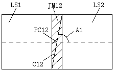
[0041] Such as Figure 1-4 As shown, the large-format multi-laser interface scanning method based on powder bed additive manufacturing includes the following steps:

[0042] The first step is to divide the large-format dual-laser working surface based on powder bed additive manufacturing;

[0043] In the second step, the diagonal C12 is rotated around the center point PC12, and the rotation angle changes with the number of model layers;

[0044] In the third step, the 3D model of the parts is sliced ​​and layered according to the layer thickness parameters required by the laser selective melting additive manufacturing process, and each layer is numbered.

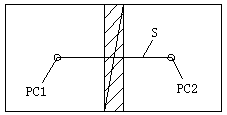
[0045] Among them, the area division includes that the scanning range of the laser scanning heads LS1 and LS2 is a square area with a side length D, the center points of the laser scanning heads LS1 and LS2 are respectively PC1 and PC2, and the distance between the two points of PC1 and PC2 is S, The overlapping area is JM...

Embodiment 2

[0057] Such as Figure 1-4 As shown, the large-format multi-laser interface scanning method based on powder bed additive manufacturing includes the following steps:

[0058] The first step is to divide the large-format dual-laser working surface based on powder bed additive manufacturing;

[0059] In the second step, the diagonal C12 is rotated around the center point PC12, and the rotation angle changes with the number of model layers;

[0060] In the third step, the 3D model of the parts is sliced ​​and layered according to the layer thickness parameters required by the laser selective melting additive manufacturing process, and each layer is numbered.

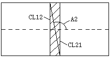
[0061] Among them, the area division includes that the scanning range of the laser scanning heads LS1 and LS2 is a square area, the center points of the laser scanning heads LS1 and LS2 are respectively PC1 and PC2, the distance between the two points of PC1 and PC2 is S, and the overlapping area is JM12 And JM12 is a rect...

Embodiment 3

[0072] Such as Figure 1-4 As shown, the large-format multi-laser interface scanning method based on powder bed additive manufacturing includes the following steps:

[0073] The first step is to divide the large-format dual-laser working surface based on powder bed additive manufacturing;

[0074] In the second step, the diagonal C12 rotates around the center point PC12, and the rotation angle changes with the number of model layers;

[0075] In the third step, the 3D model of the parts is sliced ​​and layered according to the layer thickness parameters required by the laser selective melting additive manufacturing process, and each layer is numbered.

[0076] Among them, the area division includes that the scanning range of the laser scanning heads LS1 and LS2 is a square area, the center points of the laser scanning heads LS1 and LS2 are respectively PC1 and PC2, the distance between the two points of PC1 and PC2 is S, and the overlapping area is JM12 And JM12 is a rectang...


PUM


Abstract

The technical points of the large-format multi-laser variable junction scanning method based on powder bed additive manufacturing include the following steps. In the first step, the diagonal line is rotated around the center point, and the rotation angle changes with the number of model layers. In the third step, the 3D model of the part is sliced ​​and layered according to the layer thickness parameters required by the laser selective melting additive manufacturing process. Number each layer; using this technical solution, large-scale scanning and filling are realized through multi-laser combination, and the scanning path and parameter design functions of multi-model layers are realized at the same time, which effectively solves the problem of laser selective melting and forming in the center and edge area of ​​the cylinder. The structural uniformity of the formed parts and the key technical problems such as stress and deformation ensure the structural uniformity of the formed parts in the center and edge areas of the forming cylinder.

Description

technical field [0001] The invention relates to the technical field of laser selective melting and additive manufacturing, in particular to a large-format multi-laser transition surface scanning method based on powder bed additive manufacturing. Background technique [0002] Laser selective melting additive manufacturing technology is an advanced manufacturing technology based on the idea of ​​discrete accumulation forming. It does not require molds. By discretizing the 3D model of the part into a series of orderly micron-scale thin layers along a certain direction, the high-brightness laser is used as the heat source. According to the contour information of each layer, metal powder is melted layer by layer, and parts of any complex shape are directly manufactured, only heat treatment and surface finishing parts are required; it has the characteristics of greatly reducing manufacturing processes, shortening production cycle, saving materials and funds; it is a high-end product...

Claims


Application Information

Patent Timeline
Patent Type & Authority Patents(China)
IPC IPC(8): B22F3/105B33Y10/00B33Y50/02
CPCB33Y10/00B33Y50/02B22F10/00B22F12/45B22F10/28Y02P10/25
Inventor 李怀学巩水利黄柏颖胡全栋孙帆丁利王玉岱
Owner AVIC BEIJING AERONAUTICAL MFG TECH RES INST
Why Eureka
Try Eureka