Eureka AIR delivers breakthrough ideas for toughest innovation challenges, trusted by R&D personnel around the world.

A method for detecting and locating oil and gas pipeline bursts

A technology for oil and gas pipelines and pipelines, which is applied to pipeline systems and can solve problems such as difficulty in determining the degree of leakage, complex pipeline wiring structure, noise interference, etc.

Active Publication Date: 2020-03-10
PETROCHINA CO LTD
View PDF5 Cites 0 Cited by
  • Summary
  • Abstract
  • Description
  • Claims
  • Application Information

AI Technical Summary

Problems solved by technology

[0005] In the prior art, for the pressure gradient method, on the one hand, due to changes in the geographical environment and climate, the need for production and the increase in pipeline branches, the pipeline wiring structure is complicated, and abnormal characteristics may appear in the case of no leakage, resulting in errors. Alarm phenomenon, on the other hand, due to the change of operating conditions when the compressor starts and stops, abnormal characteristics may also appear in the case of no leakage, resulting in false alarm phenomenon; for the sonic wave method, the difference in the shape of the leakage port has a great influence on the characteristics of the leakage sound wave The influence is relatively large. The frictional noise interference between the medium transported by the pipeline and the inner wall of the pipeline, and the false alarm caused by the noise interference when the valve operates has yet to be solved, and it is difficult to determine the degree of leakage. A large number of personnel are required, and it is difficult to solve the problems of signal record transmission and accurate and reliable clock synchronization

Method used


Image

  • A method for detecting and locating oil and gas pipeline bursts
  • A method for detecting and locating oil and gas pipeline bursts
  • A method for detecting and locating oil and gas pipeline bursts

Examples


Embodiment Construction

[0044] In order to make the technical solutions and advantages of the present invention clearer, the embodiments of the present invention will be further described in detail below in conjunction with the accompanying drawings.

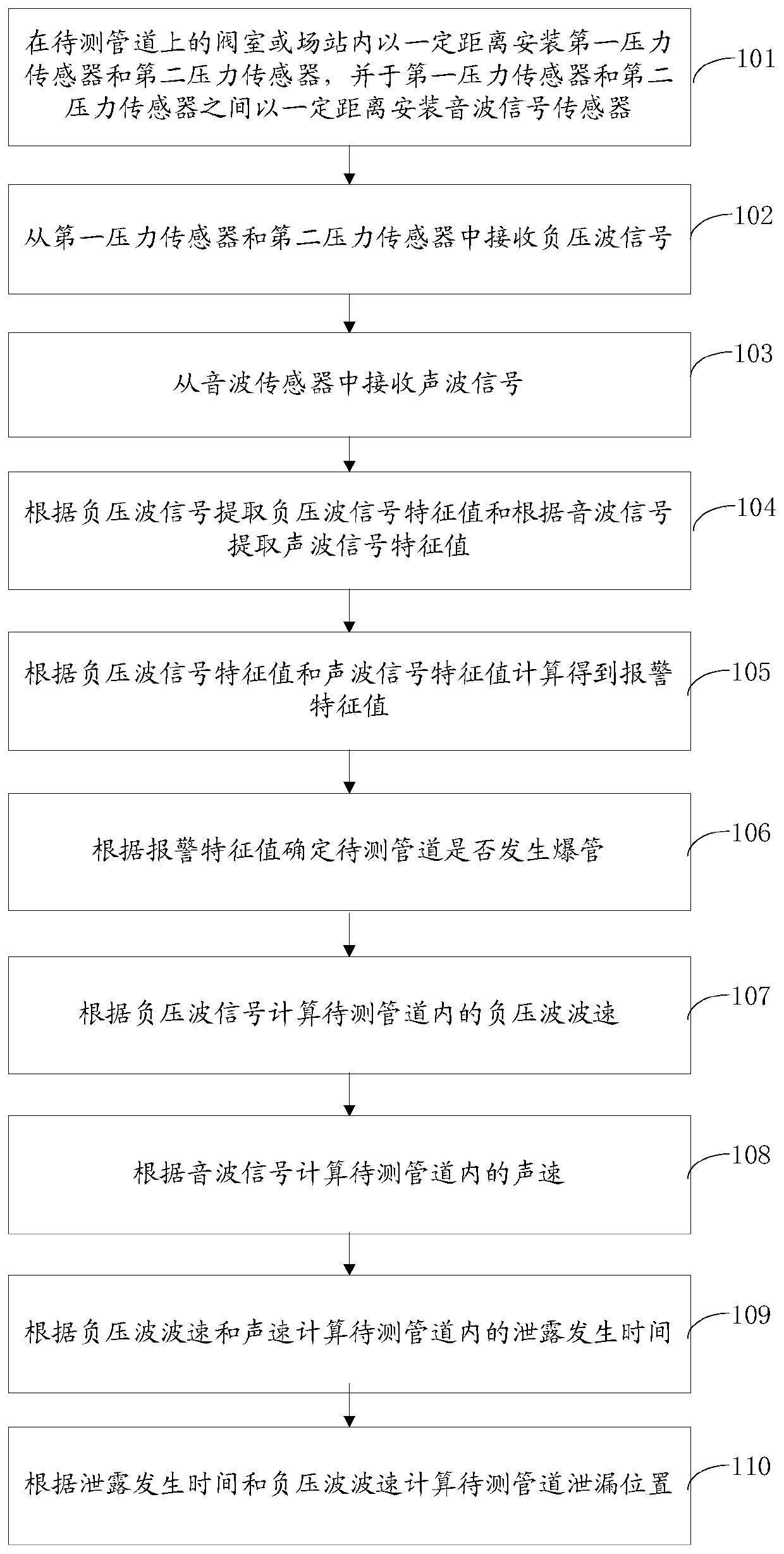
[0045] An embodiment of the present invention provides a method for detecting and locating oil and gas pipeline bursts, see figure 1 , the method flow is as follows:

[0046] Step 101: installing a first pressure sensor and a second pressure sensor at a certain distance in a valve chamber or a field station on the pipeline to be tested, and installing an acoustic signal sensor at a certain distance between the first pressure sensor and the second pressure sensor;

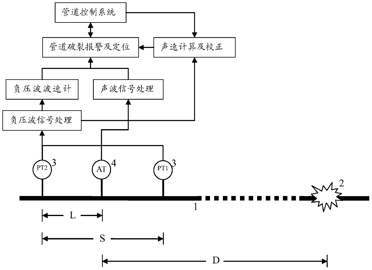
[0047] Specifically, as figure 2 As shown, the first pressure sensor PT1 and the second pressure sensor PT2 are installed at a certain distance L in the valve chamber or field station on the pipeline to be tested, and a certain distance between the first pressure sensor PT1 and the second ...


PUM


Abstract

The invention discloses an oil and gas pipeline burst detecting and positioning method, and belongs to the technical field of oil and gas storage and transportation. The method comprises the steps that a first pressure sensor, a second pressure sensor and a sound wave signal sensor are arranged in a valve chamber or a field station on a pipeline to be detected at a certain distance, a negative pressure wave signal and a sound wave signal are received, negative pressure wave signal characteristic value and sound wave signal characteristic value are extracted to calculate alarm characteristic value, whether the pipeline to be detected bursts or not is determined, and according to the negative pressure wave signal and the sound wave signal, the leakage position of the pipeline to be detectedis calculated. According to the oil and gas pipeline burst detecting and positioning method, in combination with advantages of multiple detection methods, the false alarm probability is reduced, alarminformation can be conveniently found in time, meanwhile, the oil and gas pipeline burst positioning method is provided, the leakage position of the pipeline to be detected can be positioned, and theneeded device is compact in mounting, convenient to operate and capable of achieving independent positioning.

Description

technical field [0001] The invention relates to the technical field of oil and gas storage and transportation, in particular to a method for detecting and locating bursts of oil and gas pipelines. Background technique [0002] Oil and gas pipelines are an important way of oil and gas transportation. If the oil and gas pipeline leaks, it will not only cause huge economic losses and waste of resources, but also bring safety and pollution problems, seriously threatening people's lives, property and living environment safety. Therefore, it is particularly important to comprehensively detect and locate oil and gas pipeline bursts. [0003] At present, there are two main real-time pipeline rupture detection methods for oil and gas pipelines, namely the pressure gradient method and the acoustic wave method. The pressure gradient method is to install sensors at each shut-off valve along the pipeline, and determine the leakage and leakage degree of the pipeline according to the gra...

Claims


Application Information

Patent Timeline
Patent Type & Authority Patents(China)
IPC IPC(8): F17D5/06G01M3/24
CPCF17D5/06G01M3/243
Inventor 李洪烈钱祖国董铁军常大伟朱雀禹扬张石超解立晓王多才赵廉斌
Owner PETROCHINA CO LTD
Why Eureka
Eureka Blog
Learn More