A non-condensable gas tube heat exchanger with variable length of flow stabilization device

A technology of shell-and-tube heat exchangers and flow stabilization devices, which is applied in the directions of indirect heat exchangers, heat exchanger types, heat transfer modification, etc., and can solve the problem of vibration and noise of gas-liquid two-phase flow heat exchangers. Unable to achieve the uniformity of the gas phase and liquid phase, and the disturbance of the heat exchange tubes cannot be guaranteed, so as to achieve the effect of reducing the noise level, reducing noise and vibration, and smooth flow

Inactive Publication Date: 2019-01-18
SHANDONG UNIV
View PDF1 Cites 0 Cited by
  • Summary
  • Abstract
  • Description
  • Claims
  • Application Information

AI Technical Summary

Problems solved by technology

However, the above-mentioned technology does not solve the vibration and noise problems in the gas-liquid two-phase flow heat exchanger, and the above-mentioned solution has a complex structure, and because of the size of the thorns, the disturbance on the entire cross-section in the middle of the heat exchange tube cannot be guaranteed. The overall uniformity of the gas phase and liquid phase cannot be achieved, and the noise and vibration problems are still serious
[0005] The current arrangement of flow stabilizing devices to solve vibration and noise is not arranged according to the laws of shock absorption and noise reduction, resulting in excessive flow resistance in the pipe and poor effect of shock absorption and noise reduction

Method used


Image

  • A non-condensable gas tube heat exchanger with variable length of flow stabilization device
  • A non-condensable gas tube heat exchanger with variable length of flow stabilization device
  • A non-condensable gas tube heat exchanger with variable length of flow stabilization device

Examples


Embodiment Construction

[0041] The specific embodiments of the present invention will be described in detail below in conjunction with the accompanying drawings.

[0042] In this article, if there is no special explanation, when it comes to formulas, " / " means division, and "×" and "*" mean multiplication.

[0043] It should be noted that, unless otherwise specified, the two-phase flow mentioned in the present invention is a gas-liquid two-phase flow, and the gas here is an insoluble or poorly soluble gas, that is, the gas will not dissolve in the liquid during the heat exchange process.

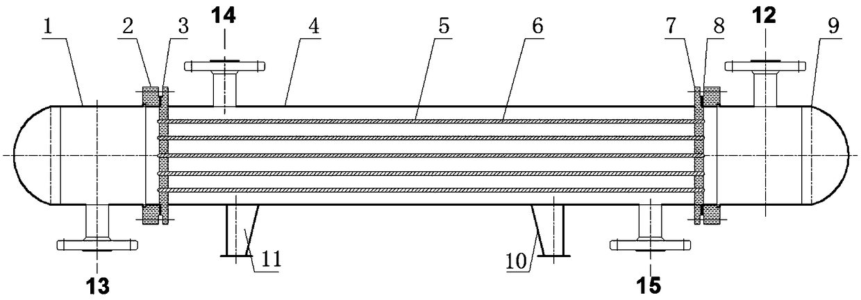
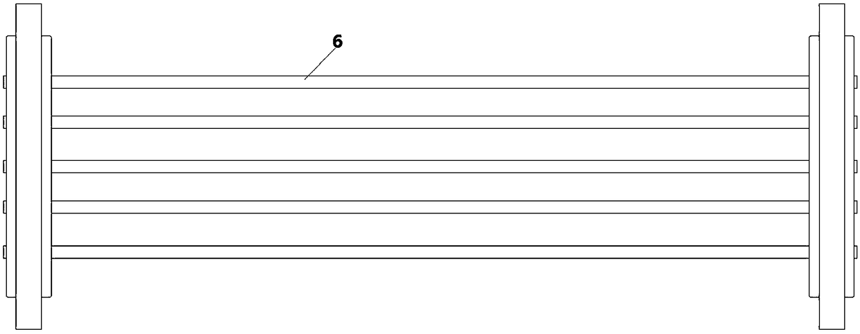
[0044] Such as figure 1 A shell-and-tube heat exchanger is shown, and the shell-and-tube heat exchanger includes a shell 4, a heat exchange tube 6, a tube-side inlet pipe 12, a tube-side outlet pipe 13, a shell-side inlet connecting pipe 14 and a shell The outlet connecting pipe 15; the heat exchange tube bundle composed of a plurality of parallel heat exchange tubes 6 is connected to the front tube sheet 3 and th...


PUM


Abstract

The present invention provides a gas-liquid two-phase flow multi-tube shell-and-tube heat exchanger, which includes a shell, and the two ends of the shell are respectively provided with heads, and the connection position between the head and the shell is set with a tube plate. The heat exchange tube is connected to the tube sheets at both ends. The gas phase in the vapor-liquid two-phase flow is an insoluble or insoluble gas, that is, the gas will not dissolve in the liquid during the heat exchange process. It is characterized in that the heat exchange tube is set for reducing A stabilizing device for vibration and noise reduction. Multiple stabilizing devices are installed in the same heat exchange tube. Along the flow direction of the fluid in the heat exchange tube, the length of the stabilizing device first gradually decreases to a certain position, and then from From a position, the length of the flow stabilizing device increases gradually. The invention provides a method for reducing the vibration of the pipeline to the greatest extent, lowering the noise level and reducing the flow resistance at the same time when the gas-liquid two-phase flow exists in the pipeline through the length change of the flow stabilizing device.

Description

technical field [0001] The invention relates to a shell-and-tube heat exchanger, in particular to a two-phase flow heat exchanger containing non-condensable gas. Background technique [0002] Two-phase flow heat exchange containing non-condensable gas widely exists in heat exchange devices, for example, non-condensable gas is mixed in the heat exchange process, or non-condensable gas is produced due to equipment aging during fluid transportation, and natural gas, for example Condensation of mixed media with different boiling points, air separation, mixed refrigerant refrigeration, petroleum or waste plastic cracking, production The main technological process of industries such as material gas production. [0003] The existence of the gas phase in the heat exchange process of the fluid containing non-condensable gas will lead to low heat exchange efficiency, worsen heat exchange, unstable fluid flow process, and lead to collision phenomenon. When the gas-liquid phase of the...

Claims


Application Information

Patent Timeline
Patent Type & Authority Patents(China)
IPC IPC(8): F28D7/16F28F13/06
CPCF28D7/1615F28F13/06
Inventor 郭春生年显勃刘勇齐超宋金圣邓伊涵
Owner SHANDONG UNIV
Why Eureka
Try Eureka