Wireless interference testing method and wireless interference testing system

A technology of wireless interference and testing method, applied in transmission system, wireless communication, transmission monitoring and other directions, can solve the problem that the interference test cannot be realized, the interference test cannot be truly restored, and the effectiveness and accuracy of the received power of the receiving equipment at the affected end can be affected. problems to improve accuracy and reproducibility, shorten test time, and improve validity and accuracy

Active Publication Date: 2018-04-03
深圳无线电检测技术研究院 +1
View PDF5 Cites 20 Cited by
  • Summary
  • Abstract
  • Description
  • Claims
  • Application Information

AI Technical Summary

Problems solved by technology

[0005] However, the setting of the DSRC terminal interference test is an external field test. In the actual test process, it is necessary to set up different types and quantities of interference sources to realize the interference test.
Due to the large number of interference source signals and the attenuation and fading of the interference source itself, it is difficult to quantify the interference signals reaching the interfered device. It takes a lot of test time and manpower to test in all scenarios, so it is impossible to achieve fast , Accurate interference test
[0006] In addition, there are existing blocking interference test methods for TD-SCDMA mobile communication terminals. When the transmitting device at the disturbed end transmits signals, it will generate radiated electromagnetic interference that leaks into space, and the radiated electromagnetic interference signal is transmitted to the receiving end of the disturbed system through space coupling. Affects the validity and accuracy of the received power of the receiving device at the disturbed end, and cannot truly restore the interference test in the laboratory conduction environment

Method used


Image

  • Wireless interference testing method and wireless interference testing system
  • Wireless interference testing method and wireless interference testing system
  • Wireless interference testing method and wireless interference testing system

Examples


Embodiment Construction

[0066] Hereinafter, exemplary embodiments of the present disclosure will be described in more detail with reference to the accompanying drawings. Although exemplary embodiments of the present disclosure are shown in the drawings, it should be understood that the present disclosure can be implemented in various forms and should not be limited by the embodiments set forth herein. On the contrary, these embodiments are provided to enable a more thorough understanding of the present disclosure and to fully convey the scope of the present disclosure to those skilled in the art.

[0067] In the prior art, the ITS terminal field interference test method first collects basic environmental data and measures the environmental noise level; measures the basic performance indicators of the ITS terminal; installs interference equipment and measures the basic performance indicators; according to a predetermined plan, in different scenarios, measure The basic performance of the disturbed device ...


PUM


Abstract

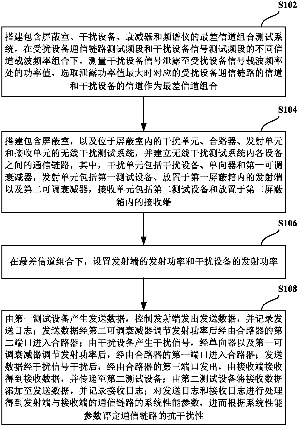
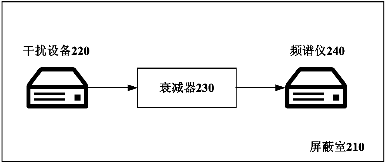
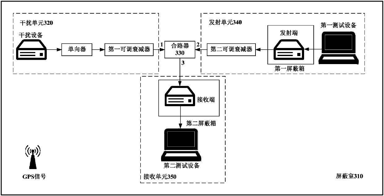
The invention provides a wireless interference testing method and a wireless interference testing system. According to the wireless interference testing method, the wireless interference testing system is set up, communication links among devices in the wireless interference testing system are established, and accordingly, anti-interference tests for LTE-V2X communication links in a shielded-roomenvironment are realized. The wireless interference testing system comprises a shielded room, an interference unit, a combiner, an emitting unit and a receiving unit, wherein the interference unit, the combiner, the emitting circuit and the receiving unit are located in the shielded room. During wireless interference testing, an emitting terminal and a receiving terminal are arranged in a first shielding box and a second shielding box respectively, so that radiation electromagnetism of the emitting terminal in lab interference tests is prevented from entering the receiving terminal to cause radiation interference, and testing effectiveness and accuracy are improved greatly. In the shielded-room environment, accurately-rationed and parameter-adjustable interference source signals can be realized by a signal generator, so that testing accuracy and reoccurrence degree are improved while testing time is shortened effectively.

Description

Technical field [0001] The present invention relates to the field of wireless communication technology, in particular to a wireless interference test method and system. Background technique [0002] At the beginning of the 21st century, automobile technology and radio technology showed a trend of mutual integration. The proposal of ITS (Intelligent Transportation System) realized the integration of information interaction among vehicles, pedestrians and roadside infrastructure. With the popularization of LTE (Long Term Evolution) technology, especially LTE-D2D (Long-Term Evolution Device-to-Device, a communication service that supports communication between devices and devices in an LTE cellular system) The formulation of the standard makes it possible to realize direct communication between vehicles, roads, and people based on LTE technology, so as to meet the low-latency and high-reliability communication requirements between vehicles, roads, and people. LTE-V2X (Long-Term Evo...

Claims


Application Information

Patent Timeline
Patent Type & Authority Applications(China)
IPC IPC(8): H04W24/06H04B17/345H04B17/391
CPCH04B17/345H04B17/391H04B17/3912H04W24/06
Inventor 王筠婷郭伟斌许瑞琛杜昊吕玉琦李晓帆张莎
Owner 深圳无线电检测技术研究院
Why Eureka
Try Eureka