High-precision fluid supply device
A feeding device and high-precision technology, which is applied to devices and coatings that apply liquid to the surface, can solve problems such as being restricted, and achieve the effects of improving durability and service life, high accuracy and convenient maintenance.
- Summary
- Abstract
- Description
- Claims
- Application Information
AI Technical Summary
Problems solved by technology
Method used
Image
Examples
Embodiment 1
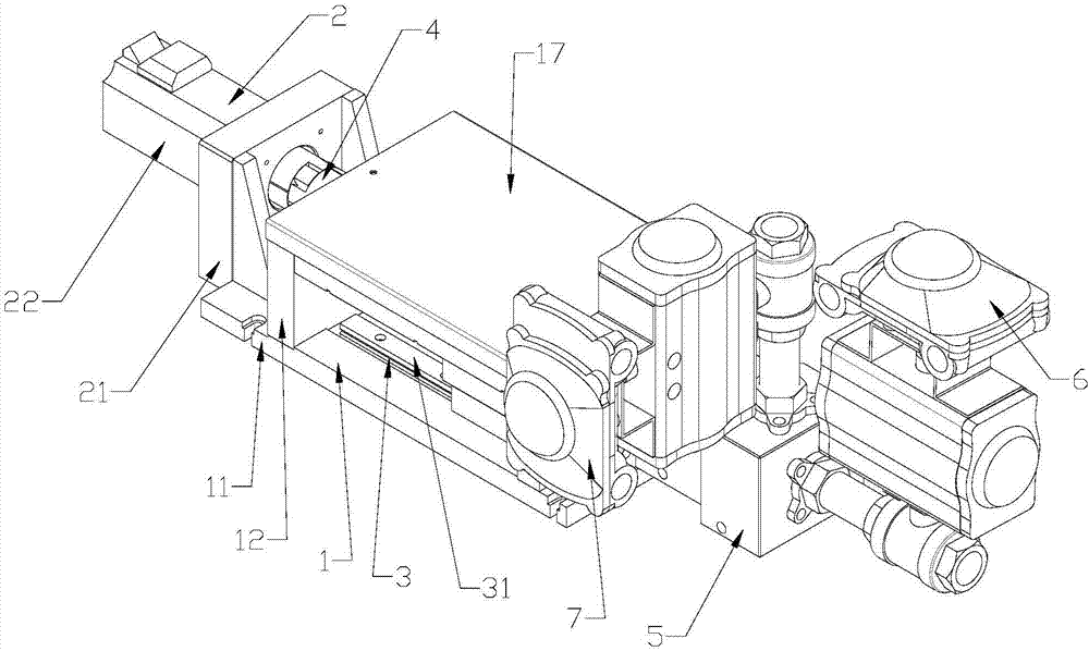
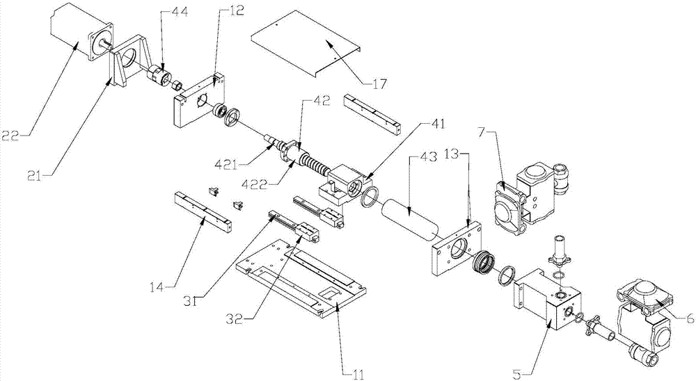
[0021] Example 1 as figure 1 , 2 As shown, a high-precision fluid supply device includes a base body 1, a power device 2 installed on the base body 1 and a guide rail device 3 installed on the base body 1, and also includes a The transmission device 4 on the guide rail device 3, the transmission device 4 includes a connecting block 41 installed on the guide rail device 3, a screw device 42 and a plunger rod 43 connected by the connecting block 41, the One end of the screw device 42 is connected with the power device 2, the other end of the screw device 42 is connected with the plunger rod 43, and the power device 2 will rotate through the screw device 42 Transformed into the linear reciprocating motion of the plunger rod 43, the base body 1 is also connected with a plunger cylinder 5, and the plunger cylinder 5 is provided with a glue inlet valve actuator 6 and a glue outlet valve actuator. Mechanism 7 (the valve actuator here is a combination of a ball valve and an actuator...
Embodiment 2
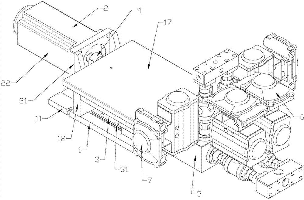
[0029] Example 2 as image 3 , 4 As shown, it is a double glue-out working mode setting. The scheme of embodiment 2 is a better technical scheme expanded on the basis of the scheme of above-mentioned embodiment 1, and the principle of glue-out and material supply is roughly the same as that of embodiment 1. The difference in structure is that the plunger cylinder body 5 in embodiment 2 is provided with two cylinders, on which are connected two parallel glue inlet valve actuators 6 and two parallel glue outlet valve actuators 7, Correspondingly, there are two parallel transmission devices 4, and the two transmission devices 4 are respectively provided with a transmission gear 8 at one end connected to the power device 2, and the transmission gears 8 are meshed with each other, so that When one transmission device 4 drives the corresponding plunger rod 43 to move forward, the other transmission device 4 drives the corresponding plunger rod 43 to move backward. That is to say, ...
Embodiment 3
[0031] Example 3 as Figure 5 As shown, it differs from Embodiment 1 in that the glue-in valve actuator 6 and the glue-out valve actuator 7 are changed from a combination of a ball valve and an actuator to a combination of a cylinder and a seal. The glue cylinder mechanism 60 and the glue outlet cylinder mechanism 70 respectively replace the glue inlet valve actuator 6 and the glue outlet valve actuator 7 in Embodiment 1. Embodiment 3 ensures that the technical function and effect are the same as Embodiment 1. Compared with Embodiment 1, it has the advantages of compact structure, more convenient installation, repair and maintenance.
PUM
 Abstract
Description
Claims
Application Information
 - R&D
- Intellectual Property
- Life Sciences
- Materials
- Tech Scout
- Unparalleled Data Quality
- Higher Quality Content
- 60% Fewer Hallucinations
Browse by: Latest US Patents, China's latest patents, Technical Efficacy Thesaurus, Application Domain, Technology Topic, Popular Technical Reports.
© 2025 PatSnap. All rights reserved.Legal|Privacy policy|Modern Slavery Act Transparency Statement|Sitemap|About US| Contact US: help@patsnap.com


