
Robot assembly method

An assembly method and robot technology, applied in the field of robots, can solve problems such as large fluctuations in actual effects, lack of operation methods, and spending a long time in pondering and groping, so as to improve installation quality and assembly efficiency, reduce installation errors, and reduce The effect of the number of debugs

Active Publication Date: 2018-04-06
广东天机机器人有限公司
View PDF5 Cites 1 Cited by
  • Summary
  • Abstract
  • Description
  • Claims
  • Application Information

AI Technical Summary

Problems solved by technology

The above robot assembly technology only relies on the experience of technicians to operate. Each technician has different experience and there is no standard operation method, which makes the actual effect of the assembled product fluctuate greatly, and the technicians need to spend a long time pondering and groping. Only then can the input gear and output gear cooperate to reach a normal state, so that the assembly efficiency of the robot is low

Method used


Image

  • Robot assembly method
  • Robot assembly method
  • Robot assembly method

Examples


Embodiment Construction

[0027] In order to facilitate the understanding of the present invention, the present invention will be described more fully below with reference to the associated drawings. Preferred embodiments of the invention are shown in the accompanying drawings. However, the present invention can be embodied in many different forms and is not limited to the embodiments described herein. On the contrary, these embodiments are provided to make the understanding of the disclosure of the present invention more thorough and comprehensive.

[0028] It should be noted that when an element is referred to as being “fixed” to another element, it can be directly on the other element or there can also be an intervening element. When an element is referred to as being "connected to" another element, it can be directly connected to the other element or intervening elements may also be present.

[0029] Unless otherwise defined, all technical and scientific terms used herein have the same meaning as...


PUM


Abstract

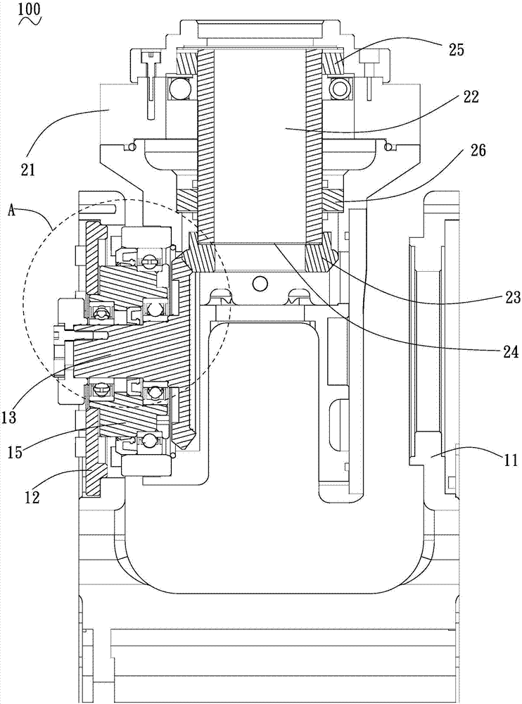
The invention relates to a robot assembly method. The robot assembly method comprises the following steps that 1, an output gear assembly is installed, specifically, the thickness of a washer T2 is calculated, a driven gear and the washer T2 are installed in a connection base, a wave generator is sleeved with a second bearing and a third bearing in sequence, and the wave generator is installed inthe connection base and located above the driven gear; and S2, an input gear assembly is installed, specifically, the thickness of a washer T1 is calculated, a driving gear is sleeved with a first bearing, a bearing block and the washer T1, the driving gear is installed in the connection base and abuts against with the driven gear, and the driving gear and the bearing block are installed on a rackthrough a mounting plate. According to the robot assembly method, the assembly debugging frequency is reduced by calculating the thicknesses of the washer T1 and the washer T2, the mounting steps ofthe parts are unified so that the mounting errors between the driving gear and the driven gear can be reduced, and thus the product mounting quality and assembly efficiency are improved.

Description

technical field [0001] The invention relates to the technical field of robots, in particular to a robot assembly method. Background technique [0002] In machine manufacturing, there are often tolerances in the dimensions of machinery or machine parts. The purpose of formulating tolerances is to determine the geometric parameters of the product so that the variation is within a certain range, so as to meet the requirements of interchange or fit. During machine assembly, due to the uncertain tolerances between the parts, two robot parts of the same model cannot guarantee that their dimensions are exactly the same, and there will always be slight deviations. Especially when assembling the input gear and output gear of the robot, a slight error in the installation between the input gear and the output gear will seriously affect the operation performance of the robot. [0003] In the traditional assembly technology, in order to reduce the installation error between the input ge...

Claims


Application Information

Patent Timeline
IPC IPC(8): B23P19/00G01B21/08
CPCB23P19/00G01B21/08
Inventor 莫卓亚申舰刘涛
Owner 广东天机机器人有限公司
Learn More