
Layout scheme for pulling system in cat anchor test of wooden mold

An anchor pull test and system layout technology, which is applied in ship components, ships, transportation and packaging, etc., can solve the problem that the anchor cannot obtain smooth and smooth operation and accurate stopping points, increase the factors and variables of the test process, and greatly reduce the finish, etc. problems, to achieve the effect of stable lifting and throwing operation of anchorage, stable and smooth operation process, and effective control of stability

Inactive Publication Date: 2018-04-06
CSSC HUANGPU WENCHONG SHIPBUILDING COMPANY
View PDF5 Cites 2 Cited by
  • Summary
  • Abstract
  • Description
  • Claims
  • Application Information

AI Technical Summary

Problems solved by technology

First of all, the hemp rope has to withstand the grinding of the wooden tooling with a high friction coefficient hundreds of times. Often in the later stage of the test, although it will not crack and break, it will become a waste rope with rough burrs and a greatly reduced smoothness. Most of them need to be replaced due to increased friction, which increases the variables of the test process; and more importantly, the method of lifting and dropping anchors by one or more people is used. Due to the influence of factors such as adjustment, different passwords, and power control, power output such as forceful skewing, unevenness, and excessive force will be out of control, and the anchorage will not be able to obtain smooth operation and precise stop points; objectively, human pulling The oblique moment relative to the anchor test box will cause the weaker anchor test box to be squeezed obliquely and laterally to produce plasticity or even rigid deformation, which will directly affect the test results and cause serious inaccuracies in the results of the anchor test. as a result of

Method used


Image

  • Layout scheme for pulling system in cat anchor test of wooden mold
  • Layout scheme for pulling system in cat anchor test of wooden mold

Examples


Embodiment 1

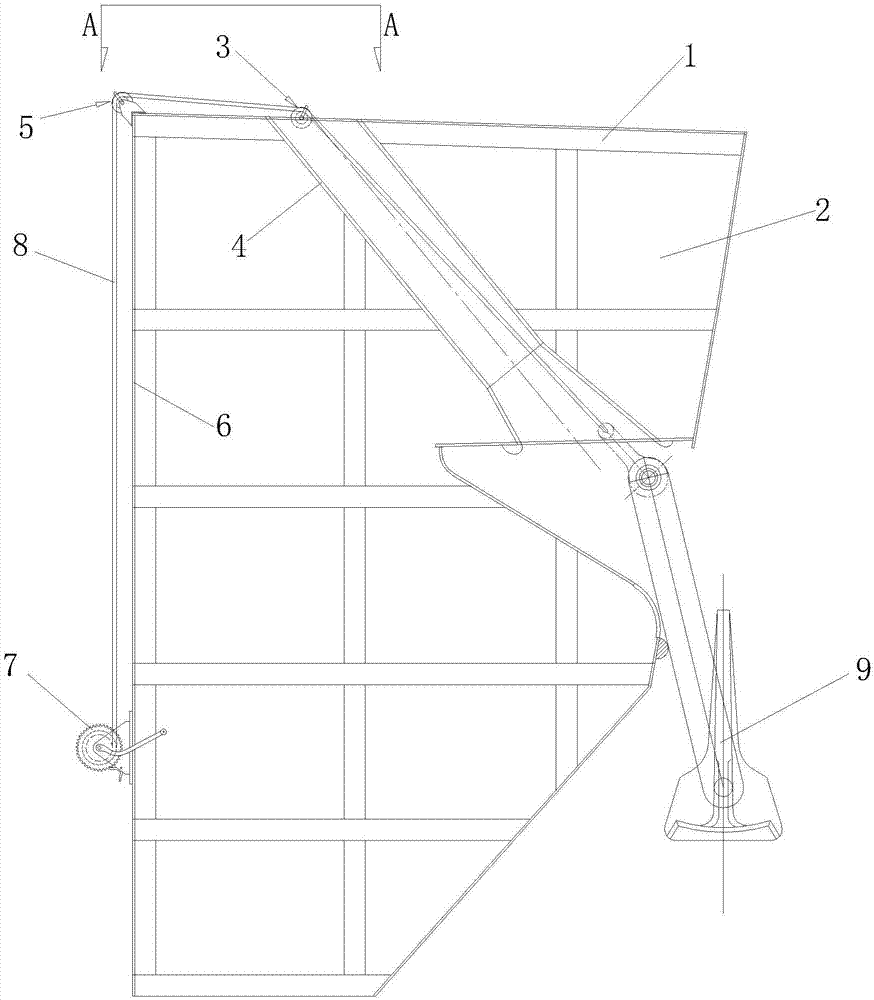
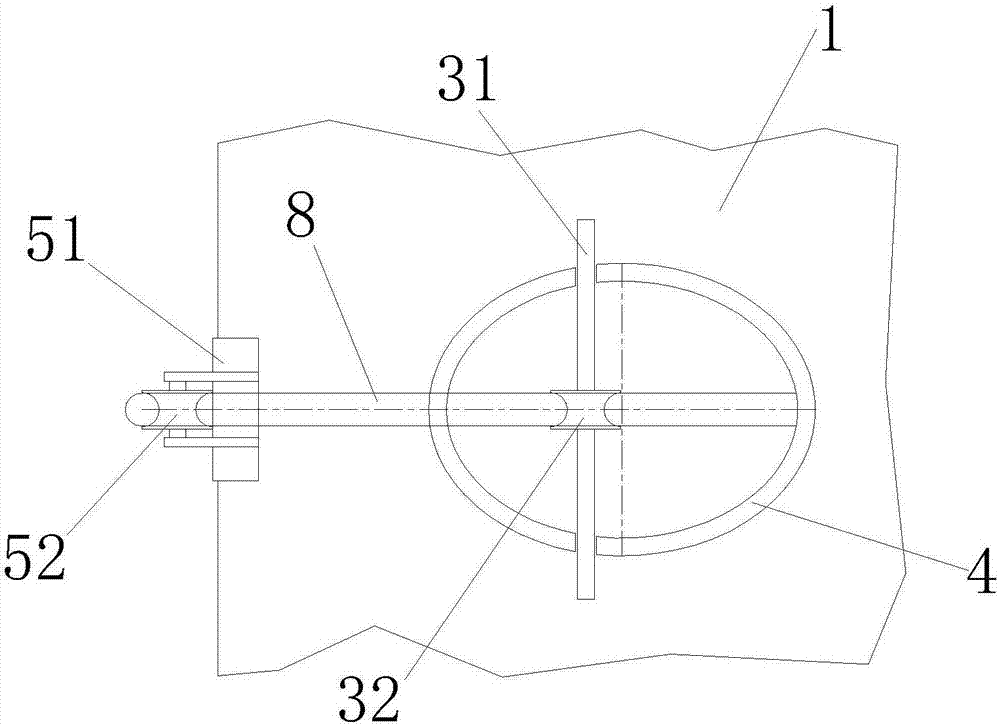
[0021] Such as figure 1 , 2 As shown, this embodiment provides a plan for the layout of the pulling system in the wooden model anchor pulling test, which is arranged on the hull deck 1 and the anchor test box 2, including:

[0022] The fairlead 3 is composed of a shaft rod 31 and a first roller 32 mounted on the shaft rod 31, and is arranged on the top of the chain barrel 4, that is, the central part of the opening between the chain shaft 4 and the deck 1;

[0023] The angle wheel device 5 is composed of a support 51 and a second roller 52 installed on the support 51, arranged on the intersection line of the deck 1 of the anchor test box 2 behind the fairlead 3 and the 6 sides of the box back plate superior;

[0024] The self-locking manual winch 7 is arranged on the box backboard 6 of the anchor test box 2 directly below the corner wheel 5;

[0025] One end of the nylon rope 8 is connected with the anchorage 9, and the other end is connected with the self-locking manual wi...


PUM


Abstract

The invention relates to a layout scheme for a pulling system in a cat anchor test of a wooden mold. The layout scheme has the advantages that the tooling part layout is reasonable, an implemented technology is simple and practical, and adopted tooling parts are durable, can be recycled and are high in implementing cost performance. The essence is to change a power transmission mode as an intake point; a conventional manual direct pulling mode is changed into an indirect transmission power mode with a self-locking type manual winch as a carrier, the power output directionality, stability and continuity are effectively controlled, an anchorage device obtains a constant traction more easily to make the running process smooth and steady, and the code requirements on anchorage device putting away and releasing in enterprise standards are met. When the pulling system designed by adopting the layout scheme is adopted to perform the cat anchor test of the wooden mold, not only is labor saved,but also the anchoring device anchorage operation in the test process is as stable as that in a true ship test, and the credibility of cat anchor test results is ensured.

Description

technical field [0001] The invention relates to the field of shipbuilding, in particular to an arrangement scheme of a pulling system in a wooden formwork anchor pulling test. Background technique [0002] As a substitute for the actual ship anchor test, the wooden model anchor test is the basis for obtaining real test results by simulating the stable anchor lifting operation of the real ship; at the same time, according to the enterprise standards for wooden anchor test , every time the anchor is thrown, it needs uniform force to ensure the uniform operation of the anchor, and it is required that the anchor can stop smoothly at any time during the test. In the anchor pulling test of the first-made ship wooden model, the lifting and throwing operation of wooden anchors is accompanied by the test. The rationality of the pull system layout of the tool is very important. [0003] At present, in the anchor pulling test of wooden formwork, simple tools such as hemp ropes and wo...

Claims


Application Information

Patent Timeline
Patent Type & Authority Applications(China)
IPC IPC(8): B63B9/00B63B21/10B63B21/16
CPCB63B21/10B63B21/16B63B71/00
Inventor 刘元斌
Owner CSSC HUANGPU WENCHONG SHIPBUILDING COMPANY
Learn More