Novel distributed anaerobic treatment equipment

An anaerobic treatment equipment and decentralized technology, applied in the field of water treatment, can solve the problems of long construction period, easy corrosion of steel bars, high manufacturing costs, etc., and achieve the effect of lightweight products, strong biological adhesion, and economical and reliable equipment

Pending Publication Date: 2018-04-06
LINGZHI ENVIRONMENTAL PROTECTION CO LTD +1
View PDF3 Cites 0 Cited by
  • Summary
  • Abstract
  • Description
  • Claims
  • Application Information

AI Technical Summary

Problems solved by technology

The disadvantage of using brick as the main material is that it occupies a large area, the construction period is long, and it is easy to leak; the disadvantage of using steel bar as the main material is that the steel bar is easy to corrode and the manufacturing cost is high; Many, and the production of FRP is a highly polluting industry

Method used


Image

  • Novel distributed anaerobic treatment equipment
  • Novel distributed anaerobic treatment equipment
  • Novel distributed anaerobic treatment equipment

Examples


Embodiment 1

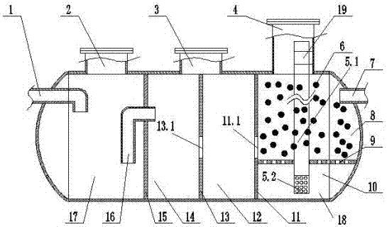
[0020] Embodiment 1: A new type of decentralized anaerobic treatment equipment, including a horizontal shell, a water inlet 1 opened at the left end of the horizontal shell, a water outlet 7 opened at the right end of the horizontal shell, and set in the horizontal shell The three bulkheads are the first, second, and third bulkheads (15, 13, 11) from left to right, and the three bulkheads divide the horizontal shell into four from left to right. The chambers respectively constitute anaerobic zone I 17 (first chamber), anaerobic zone II 14 (second chamber), anaerobic zone III 12 (third chamber), aerobic precipitation zone 18 (fourth chamber) room), the first manhole 2 is opened at the top shell position of the first chamber, the second manhole 3 is opened at the top shell position of the second bulkhead 13 between the second and third chambers, and the fourth A third manhole 4 is provided at the top shell of the chamber, a diversion pipe 16 is provided on the first bulkhead 15,...

Embodiment 2

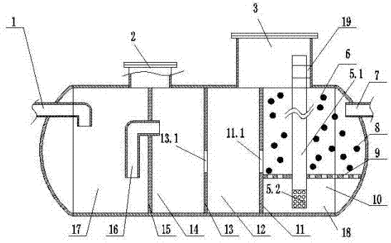
[0021] Embodiment 2: Referring to Embodiment 1, a first manhole 2 is provided at the top shell position of the first bulkhead 15 in the middle of the first and second chambers, and the third bulkhead in the middle of the third and fourth chambers 11 A second manhole 3 is provided at the upper top shell position.

Embodiment 3

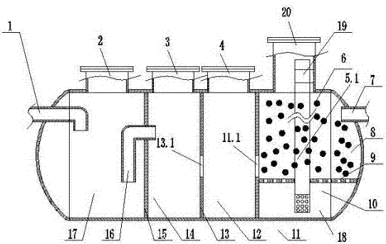
[0022] Embodiment 3: Referring to Embodiment 1, a first manhole 2 is provided at the top shell position of the first chamber, a second manhole 3 is opened at the top shell position of the second chamber, and a top shell of the third chamber is provided. A third manhole 4 is opened at the body position, and a fourth manhole 20 is opened at the top shell position of the fourth chamber.

[0023] In the above-mentioned embodiment 1 or 2 or 3, the main body of a new type of distributed anaerobic treatment equipment is integrated injection molding.


PUM


Abstract

The invention relates to novel distributed anaerobic treatment equipment, comprising a horizontal type shell, a water inlet formed at the left end of the horizontal type shell, a water outlet formed at the right end of the horizontal type shell, and three shifting boards arranged in the horizontal type shell, wherein the three shifting boards comprise a first shifting board, a second shifting board and a third shifting board which are sequentially arranged from left to right; the horizontal type shell is divided into four chambers from left to right by means of the three shifting boards, and the four chambers are respectively an anaerobic area I (the first chamber), an anaerobic area II (the second chamber), an anaerobic area III (the third chamber) and an aerobiotic precipitation area (the fourth chamber); the first shifting board is provided with a diversion feces through pipe; the second shifting board and the third shifting board are respectively provided with a first overflow holeand a second overflow hole which are used for communicating the adjacent areas; a porous mud-permeable packing support plate is arranged at the middle lower end of the fourth chamber and is used fordividing the fourth chamber into an upper chamber and a lower chamber; the two chambers are respectively an aerobiotic area and a precipitation area from top to bottom; the filler is added in the upper part of the support plate; the fourth chamber is internally provided with a mud absorbing pipe; the mud absorbing pipe is connected with an exhaust inlet of a fan by means of a pipeline.

Description

technical field [0001] The invention belongs to the field of water treatment, specifically relates to new rural sewage treatment equipment, and is a new type of distributed anaerobic treatment equipment that is energy-saving, environmentally friendly, economical and reliable. Background technique [0002] Now, with the increasingly serious pollution of rural life, rural sewage treatment is imminent. Among them, the rural sewage treatment includes the centralized treatment method of sewage interception and collection pipes, and the decentralized treatment method. For rural sewage treatment, the centralized treatment of sewage interception pipes is difficult to construct, the construction cost is high, and the maintenance cost is high. Distributed treatment generally adopts decentralized anaerobic treatment equipment. Due to the lack of a standard system, the quality of decentralized anaerobic treatment equipment is often uneven. Conventional anaerobic treatment equipment is...

Claims


Application Information

Patent Timeline
Patent Type & Authority Applications(China)
IPC IPC(8): C02F3/28C02F3/12
CPCC02F3/12C02F3/28C02F2203/006Y02W10/10
Inventor 王治政邵飞姜宇辰范旭朱文雅董晓柯
Owner LINGZHI ENVIRONMENTAL PROTECTION CO LTD
Why Eureka
Try Eureka