Liquid flow control device of electronic display glass platinum channel

A platinum channel and electronic display technology, applied in glass manufacturing equipment, glass furnace equipment, manufacturing tools, etc., can solve the problems of difficult control, etc., and achieve the effect of convenient use, simple structure, and low transformation cost

Pending Publication Date: 2018-04-06
(CNBM) BENGBU DESIGN & RES INST FOR GLASS IND CO LTD
2 Cites 1 Cited by

AI-Extracted Technical Summary

Problems solved by technology

In the Chinese patent "Method and Device for Controlling Platinum Channel Outlet Flow" (...

Method used

Be provided with breach 3 symmetrically on glass outlet channel 2, all be provided with the slide block 4 of corresponding cooperation in each breach 3 and form movable section, described slide block 4 is made of refractory material, and thickness is greater than glass The thickness of the refractory lining of the liquid outle...

Abstract

The present invention is a liquid flow control device for an electronic display glass platinum channel, which includes: a glass liquid outlet (2), characterized in that a notch (3) is symmetrically arranged on the glass liquid outlet (2), and a gap (3) is arranged on the notch There are corresponding matching sliders (4) inside, a platinum layer (5) is arranged on the inner side of the slider (4), and a steel structure outer plate (6) is arranged on the outer side of the slider (4). The steel structure outer plate (6) is provided with a connecting seat corresponding to the push-pull device. The invention has the advantages of simple structure, convenient use, precise control of glass liquid flow, direct transformation on existing equipment, and low transformation cost.

Application Domain

Glass furnace apparatus

Technology Topic

Steel platesPush pull +3

Image

  • Liquid flow control device of electronic display glass platinum channel

Examples

  • Experimental program(1)

Example Embodiment

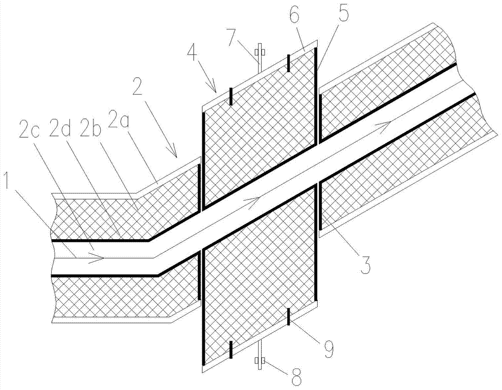
[0014] like figure 1 As shown, a flow control device for electronic display glass platinum channel, it includes: glass liquid outlet 2, the glass liquid outlet 2 includes a steel outer wall 2a, and a refractory The inner lining 2b is provided with a platinum paste layer 2d inside the refractory inner lining 2b, and the inner side of the platinum paste layer is a flow channel 2c corresponding to the molten glass 1 .
[0015] There are notches 3 symmetrically arranged on the glass outlet channel 2, and a corresponding sliding block 4 is provided in each notch 3 to form a movable section. The slider 4 is made of refractory material, and its thickness is greater than that of the glass outlet channel. 2, the thickness of the refractory lining is to ensure that the liquid channel 2 can still be sealed after the movable section is displaced. A gap is provided between the slider 4 and the notch 3, and the width of the gap is less than 3 mm, which can ensure that the glass liquid does not leak out under the action of the surface tension of the glass liquid.
[0016] A platinum layer 5 is provided on the inner side of the slider 4 and on the mating surface between the slider 4 and the notch 3 , and a steel structure outer plate 6 is arranged on the outer side of the slider 4 , and the steel structure outer plate 6 is connected by a staple 9 and The slider 4 is matingly connected. A sliding guide plate 7 protruding horizontally outward is provided on the outer wall of the steel structure outer plate 6, and a chute 8 corresponding to it is also provided on the described sliding guide plate 7, and the chute 8 is fixed On the frame, the sliding guide plate 7 can only move horizontally under the limitation of the chute 8.
[0017] On the outer wall of the steel structure outer plate 6, there is a connecting seat (not shown in the figure) corresponding to the push-pull device, and the output shaft of the push-pull device and the sliding guide plate 7 are distributed parallel to each other.
[0018] The arrows in the figure indicate the flow direction of the glass liquid in the glass outlet channel.
[0019] working principle:
[0020] According to the needs, the output shaft of the push-pull device is controlled to expand and contract, and then the slider is displaced in the gap, thereby changing the inner diameter of the glass outlet channel, thereby achieving the purpose of controlling the amount of glass liquid flowing through the glass outlet channel. In actual use, only the slider on one side can be lifted to make it displace to the inside of the glass outlet, or the sliders on both sides can be controlled to simultaneously displace to the inside of the glass outlet.

PUM

no PUM

Description & Claims & Application Information

We can also present the details of the Description, Claims and Application information to help users get a comprehensive understanding of the technical details of the patent, such as background art, summary of invention, brief description of drawings, description of embodiments, and other original content. On the other hand, users can also determine the specific scope of protection of the technology through the list of claims; as well as understand the changes in the life cycle of the technology with the presentation of the patent timeline. Login to view more.

Similar technology patents

Body condition measuring device

InactiveUS20050234351A1simple structure
Owner:DENSO CORP

Magnetic cooling apparatus and control method thereof

ActiveUS20130180263A1simple structure
Owner:SAMSUNG ELECTRONICS CO LTD

Dual-Drivetrain of Power-Assist Vehicle

InactiveUS20100181130A1enhance uphill momentumsimple structure
Owner:CHOU WEN CHENG

Classification and recommendation of technical efficacy words

  • Simple structure
  • easy to use

Sharing system for air-conditioning coat

InactiveCN107440179ASimple structureeasy to wear
Owner:QINGDAO HAIER AIR CONDITIONER GENERAL CORP LTD

Feeding device of sorter of batteries plate

InactiveCN101357717ASimple structurecooperate well
Owner:NANJING NORMAL UNIVERSITY

Emergency parachuting device and method for multiple-rotor unmanned aerial vehicle

InactiveCN103895870Aavoid aircraft crashSimple structure
Owner:SOUTH CHINA AGRI UNIV +1

Laser assisted total joint arthroplasty

InactiveUS20090234360A1easy to use
Owner:ALEXANDER VLADIMIR

Enclosure for a portable hemodialysis system

ActiveUS20090114582A1easy to use
Owner:DEKA PROD LLP
Why Eureka
Try Eureka