
Inverse-proportion three-way flow valve

A three-way flow valve, inverse proportional technology, used in multi-way valves, valve details, safety valves and other directions, can solve the problems of easy failure, high machining accuracy, high assembly requirements, large volume, etc., to achieve compact structure, reasonable structure, Small size effect

Active Publication Date: 2018-04-06
JIANGSU SIDA HEAVY IND
View PDF7 Cites 2 Cited by
  • Summary
  • Abstract
  • Description
  • Claims
  • Application Information

AI Technical Summary

Problems solved by technology

[0004] 1. The flow control part includes valve sleeve, throttle valve core, valve seat, slide valve core, spring seat, etc., which contain many parts, and these parts are slid and socketed with each other, which requires high processing accuracy and assembly. Increased production costs, and prone to failure;
[0005] 2. In order to ensure that the pressure drop generated by the oil flowing from C port to A port does not affect the pressure difference adjusted by the spool valve core and differential pressure spring, and to ensure the adjustment accuracy of the proportional flow valve, the inner hole of the spring seat and the throttle valve core are required The inner hole should be large enough, but the spring seat and valve seat of this product are both sleeved in the inner hole of the spool valve core, the spool valve core is sleeved in the inner hole of the valve sleeve, and the throttle valve core is sleeved in the inner hole of the valve seat , such a structure increases the radial dimension and axial dimension, resulting in a larger volume, which limits the application

Method used


Image

  • Inverse-proportion three-way flow valve
  • Inverse-proportion three-way flow valve
  • Inverse-proportion three-way flow valve

Examples


Embodiment Construction

[0026] The present invention will be further described in detail below in conjunction with the accompanying drawings and embodiments.

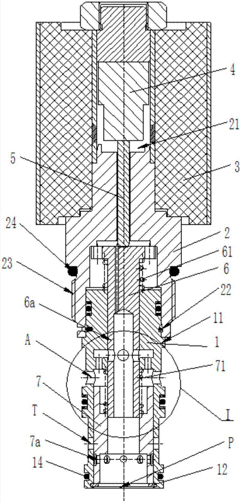
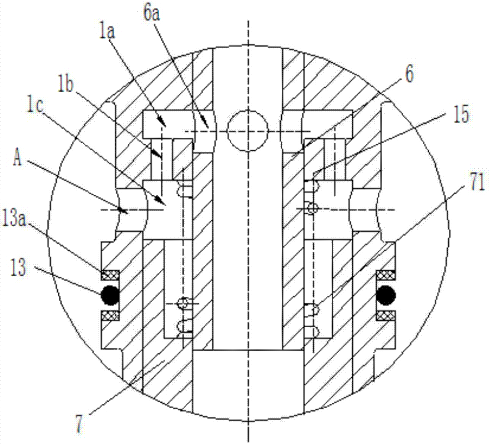
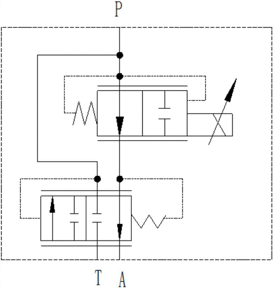
[0027] Such as Figure 1 to Figure 3 Shown is the structural representation of the present invention,

[0028] The reference signs are: P port, T port, A port, valve body 1, flow chamber 1a, flow hole 1b, differential pressure feedback chamber 1c, boss 11, retaining ring 12, first valve body sealing ring 13. Retaining ring 13a, second valve body sealing ring 14, sealing shoulder 15, valve sleeve 2, groove 21, circlip 22, external thread 23, valve sleeve sealing ring 24, proportional electromagnet 3, armature 4, top Rod 5, throttle spool 6, throttle control hole 6a, throttle spring 61, differential pressure compensation spool 7, compensation channel hole 7a, compensation spring 71.

[0029] Such as Figure 1 to Figure 3 as shown,

[0030] The inverse proportional three-way flow valve includes a valve body 1, which is provided with P port, T...


PUM


Abstract

The invention discloses an inverse-proportion three-way flow valve. The inverse-proportion three-way flow valve comprises a valve body, a P port, a T port and an A port are formed in the valve body, avalve sleeve is assembled on the upper portion of the valve body, a proportion electromagnet is assembled on the upper portion of the valve sleeve, an armature is arranged in the proportion electromagnet, and the lower surface of the armature abuts against a push rod; the push rod penetrates through the valve sleeve to abut against a throttle valve element, the lower portion of the throttle valveelement extends into the valve body, and a throttle spring is arranged between the throttle valve element and the valve body; a throttle control hole is formed in the side wall of the throttle valveelement, when a power outage occurs on the proportion electromagnet, and the throttle control hole communicates with the A port through a through-flow cavity, a through-flow hole and a differential pressure feedback cavity which are sequentially connected in the valve body; and when the proportion electromagnet is electrified, the throttle control hole is covered by a sealing convex shoulder of the valve body step by step, when a maximum voltage is given, the sealing convex shoulder can completely cover the throttle control hole. The inverse-proportion three-way flow valve has the advantages that the structure is reasonable and compact, the size is small, and control is sensitive.

Description

technical field [0001] The invention relates to the technical field of flow valve manufacturing, in particular to an inverse proportional three-way flow valve. Background technique [0002] In recent years, proportional flow valves have been used more and more in equipment such as truck-mounted cranes, aerial work vehicles, tractor rotary plows, and electric forklifts. The proportional flow valve can realize the constant pressure difference between the inlet and outlet of the flow valve, and will not be affected by load fluctuations, so that the flow rate flowing through the flow valve port is only related to the opening of the valve port, so that the flow rate can be adjusted accordingly Control, without being affected by load pressure fluctuations, and finally realize the reasonable distribution of pressure and flow of multiple oil circuits with different loads in the hydraulic system, and ensure the normal operation of various parts of the entire hydraulic system. [000...

Claims


Application Information

Patent Timeline
Patent Type & Authority Applications(China)
IPC IPC(8): F16K31/06F16K11/065F16K17/04
CPCF16K11/0655F16K17/04F16K31/0675
Inventor 陈艳艳
Owner JIANGSU SIDA HEAVY IND
Learn More