Soot blowing system and method for pi-shaped boiler furnace arch

A technology of soot blowing system and deflection angle, which is applied to the soot blowing system and soot blowing field of π-type boiler deflection angle, to achieve the effects of reducing wear, reasonable structure and avoiding tube explosion

Pending Publication Date: 2018-04-06
HUADIAN ELECTRIC POWER SCI INST CO LTD
View PDF2 Cites 8 Cited by
  • Summary
  • Abstract
  • Description
  • Claims
  • Application Information

AI Technical Summary

Problems solved by technology

[0014] The purpose of the present invention is to overcome the defects of the existing boiler deflection angle soot blower device and system, and provide a soot blowing system and soot blowing method for the π-type boiler deflection angle, which not

Method used


Image

  • Soot blowing system and method for pi-shaped boiler furnace arch
  • Soot blowing system and method for pi-shaped boiler furnace arch
  • Soot blowing system and method for pi-shaped boiler furnace arch

Examples


Embodiment

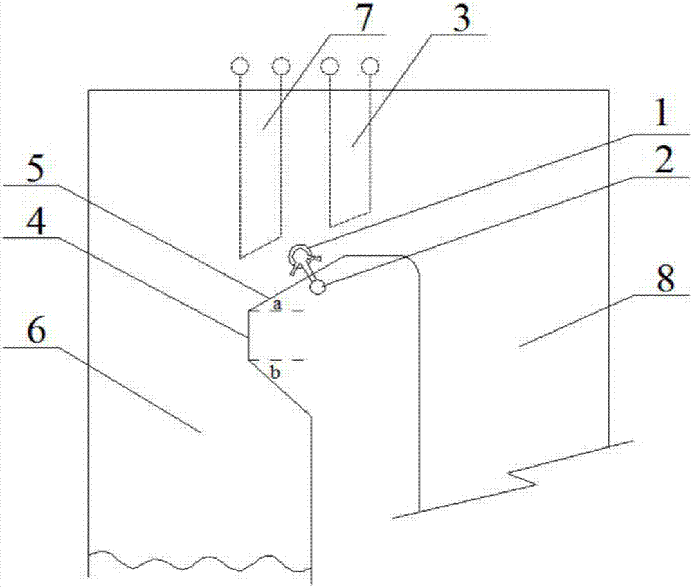
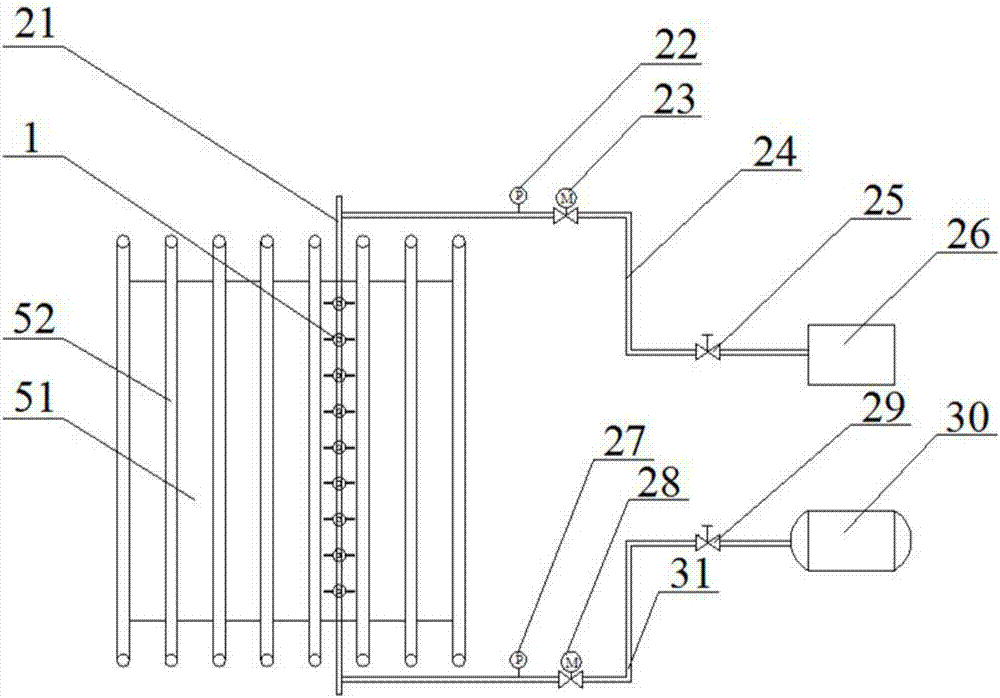
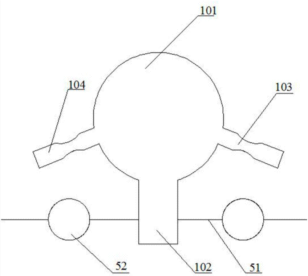
[0043] Example: see figure 1 , image 3 , the hood-type sootblower 1 of the present invention passes through the upper slope 5 of the refraction angle 4, is connected with the soot blowing medium delivery pipeline 2, and is arranged on the upper slope of the refraction angle between the high-temperature superheater 7 and the high-temperature reheater 3 superior. The upper slope 5 of the refraction angle includes a diaphragm 51 and a heat exchange tube 52. The hood type soot blower 1 is installed on the diaphragm 51 of the upper slope 5 of the refraction angle, and its structure includes a spherical hood 101, a first soot blowing nozzle 104 , the second soot blowing nozzle 103 and the inlet 102 for the purge medium. The first soot blowing nozzle 104 and the second soot blowing nozzle 103 of the present invention are obliquely downward, and the angle between the upper slope 5 of the flame angle 4 is controlled at 20° to 40°. The first soot blowing nozzle 104 The shape of the ...


PUM


Abstract

The invention discloses a soot blowing system and method for a π-type boiler flame angle. The soot blowing system utilizes the principles of pneumatic and steam fluidization to overcome the frictional force of ash deposits on the slope of the flame angle, so that the ash deposits flow to Furnace and horizontal flue and discharge. The hood type soot blower is installed on the diaphragm on the slope of the flame angle, arranged between the high temperature superheater and the high temperature reheater, passes through the upper slope of the flame angle, and is connected with the soot blowing medium delivery pipeline. The shape of the first soot blowing nozzle and the second soot blowing nozzle of the hood type soot blower is a zoom tube, which can increase the speed of the soot blowing air flow and enhance the soot blowing effect. During the soot blowing process, the compressed air firstly purges the soot accumulated on the slope of the flame angle, and then the steam purges the residual soot that is difficult to remove, and a good soot blowing effect is achieved through the composite purging mode. The invention can effectively remove the soot accumulation on the slope of the boiler flame angle, avoid excessive blow damage of the flame angle and superheater wall surface and the occurrence of pipe burst, and save energy consumption of soot blowing.

Description

technical field [0001] The invention relates to a soot blowing system and a soot blowing method, in particular to a soot blowing system and a soot blowing method for a π-type boiler refraction angle. Background technique [0002] A large amount of ash accumulation on the slope of the flame angle of a large π-type boiler is a common problem in power plants. Severe ash accumulation may cause the lower elbow of the high temperature superheater to be buried in the ash pile, which will affect the heat exchange effect, and cause local overtemperature of the pipe wall when the furnace is shut down, which will cause unsafe factors. A large amount of ash accumulated on the slope of the Zheyanjiao suddenly poured down and rushed into the furnace, interfering with the combustion and causing unimaginable adverse consequences. Research shows that the main reasons for a large amount of ash accumulation on the slope of the flame angle of a large π-type boiler include the following aspects...

Claims


Application Information

Patent Timeline
IPC IPC(8): F23J1/00F23J3/02
CPCF23J1/00F23J3/02
Inventor 王帅张庆国王学同肖冠华颜喜王永佳王凯田富中路昆
Owner HUADIAN ELECTRIC POWER SCI INST CO LTD
Why Eureka
Try Eureka