Novel soot blowing system for horizontal flue of power station boiler and work method thereof

A horizontal flue and power plant boiler technology, applied in the direction of combustion method, combustion product treatment, solid residue removal, etc., can solve the problems of tube panel collision, water wall wear, high operating temperature, etc., to avoid excessive blowing damage, solve Accumulation of dust, avoiding the effect of pipe explosion

Pending Publication Date: 2019-03-08
HUADIAN ELECTRIC POWER SCI INST CO LTD
View PDF9 Cites 0 Cited by
  • Summary
  • Abstract
  • Description
  • Claims
  • Application Information

AI Technical Summary

Problems solved by technology

During the operation of the steam soot blower, the full-stroke swing is large, and it is easy to collide with the tube panel in the refraction angle area. The steam blowing pressure is high, causing blowing damage to the high-temperature superheater, the final reheater and the refraction angle, which is serious It is easy to cause the tube burst; and affected by the gap between the tube screen, the steam soot blower cannot be arranged in the area of ​​the deflection angle, and there is a blind area of ​​soot blowing
The energy of the sonic soot blower is relatively low, and basically has no effect on the dust accumulated on the slope of the refraction angle, so that the ash cannot be taken away by the flue gas; The average operating life of the dust collector is greatly shortened, and the maintenance cost is also high
[0005] Neither the steam soot blower nor the sonic soot blower can effectively solve the problem of dust accumulation on the slope of the flame angle
At present, some boilers have a hood-type steam soot blower installed at the bottom of the horizontal flue, and the blowing medium is steam. However, after a period of operation, it is found that the water wall is severely worn, which can easily cause leakage and cause high-temperature reheaters above the water wall at the bottom of the horizontal flue. Tube burst, the consequences are very serious, so there is an urgent need for an effective system and method for ash accumulation in the horizontal flue of power plant boilers

Method used


Image

  • Novel soot blowing system for horizontal flue of power station boiler and work method thereof
  • Novel soot blowing system for horizontal flue of power station boiler and work method thereof

Examples


Embodiment Construction

[0026] The present invention will be further described in detail below in conjunction with the accompanying drawings and examples. The following examples are explanations of the present invention and the present invention is not limited to the following examples.

[0027] Example.

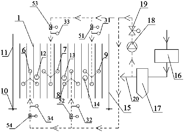
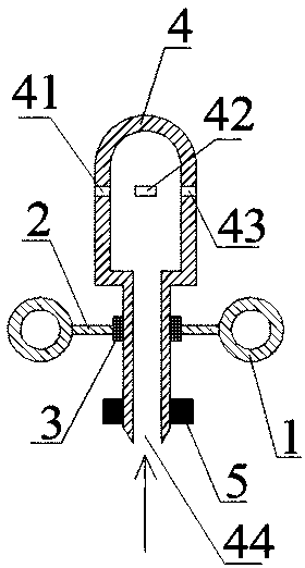
[0028] see Figure 1 to Figure 2 , the new soot blowing system for the horizontal flue of power plant boilers in this embodiment includes a water-cooled wall 1 connected by fins 2 of the water-cooled wall, and the water-cooled wall 1 is located on the left furnace wall 11 and the right furnace wall 15 Between; also includes soot blower cap 4, rotary drive device 5, first soot blower group 6, second soot blower group 7, third soot blower group 8, fourth soot blower group 9, left pressure Sensor 12, middle pressure sensor 13, rear side pressure sensor 14 and furnace smoke fan 18; first sootblower group 6, second sootblower group 7, third sootblower group 8 and fourth sootblower group 9 The first so...


PUM


Abstract

The invention relates to a novel soot blowing system for a horizontal flue of a power station boiler and a work method of the novel soot blowing system. The novel soot blowing system for the horizontal flue of the power station boiler comprises a soot blowing wind cap, a rotation driving device, a first soot blower set, a second soot blower set, a third soot blower set, a fourth soot blower set, aleft pressure sensor, a middle pressure sensor, a back pressure sensor and a flue gas fan. The four soot blower sets each comprise soot blowing wind caps. Each soot blowing wind cap comprises a firstjet opening, a second jet opening, a third jet opening and a soot blowing smoke inlet. One end of the flue gas fan is connected with a dedusting smoke outlet pipeline, and the other end of the flue gas fan is connected with the four soot blower sets. According to the novel soot blowing system for the horizontal flue of the power station boiler, the re-circulating smoke is creatively used as the soot blowing medium, the rotating type soot blowing wind caps are adopted to conduct soot blowing, accumulated dust in the horizontal flue of the boiler can be effectively removed, excessive blowing damage of a water cooled wall of the horizontal flue and pipe explosion are avoided, the pressure sensors senses the thickness of the accumulated soot of the horizontal flue, corresponding soot blowingadjusting doors are adjusted, and the soot blowing time and efficiency are effectively guided.

Description

technical field [0001] The invention relates to a soot-blowing system and method, in particular to a novel soot-blowing system and working method for the horizontal flue of a power plant boiler. Background technique [0002] A large amount of ash accumulation in the horizontal flue and refraction angle of large-scale power plant boilers is a common problem in power plants. Severe ash accumulation may cause the lower elbow of the high temperature superheater to be buried in the ash pile, which will affect the heat exchange effect, and cause local overtemperature of the pipe wall when the furnace is shut down, which will cause unsafe factors. A large amount of ash accumulated on the slope of the Zheyanjiao suddenly poured down and rushed into the furnace, interfering with the combustion and causing unimaginable adverse consequences. [0003] How to eliminate the dust accumulation on the slope of the Zhayanjiao has attracted the attention and thinking of many people. [0004]...

Claims


Application Information

Patent Timeline
Patent Type & Authority Applications(China)
IPC IPC(8): F23J3/02F23J15/02F23J15/06
CPCF23J3/02F23J15/022F23J15/06
Inventor 王帅路昆王学同张庆国王凯
Owner HUADIAN ELECTRIC POWER SCI INST CO LTD
Why Eureka
Try Eureka