Laser radar and vehicle

A laser radar and laser beam technology, applied in radio wave measurement systems, instruments, etc., can solve the problems of shortened effective detection distance, reduced transmission power, and limited projection distance of beam splitting lasers, so as to achieve energy concentration and avoid the reduction of transmission power , Solve the effect of short detection distance

Inactive Publication Date: 2018-04-06
BYD CO LTD
View PDF9 Cites 7 Cited by
  • Summary
  • Abstract
  • Description
  • Claims
  • Application Information

AI Technical Summary

Problems solved by technology

[0003] The technical shortcomings of the above-mentioned existing low-cost vehicle-mounted lidar that realizes three directions mainly include: the projection distance is limited, generally more than ten meters away
The reason for the short ranging distance is that after a single laser beam is divided into three laser beams by the beam splitting optical lens, the emission power of each split laser beam is reduced, and the detection distance is closely related to the emission power. The greater the power, the longer the detection distance. Therefore, the power of the beam splitting laser is reduced and the overall effective detection distance is shortened.

Method used


Image

  • Laser radar and vehicle
  • Laser radar and vehicle
  • Laser radar and vehicle

Examples


Embodiment Construction

[0033] Reference will now be made in detail to the exemplary embodiments, examples of which are illustrated in the accompanying drawings. When the following description refers to the accompanying drawings, the same numerals in different drawings refer to the same or similar elements unless otherwise indicated. The implementations described in the following exemplary examples do not represent all implementations consistent with the present disclosure. Rather, they are merely examples of apparatuses and methods consistent with aspects of the present disclosure as recited in the appended claims.

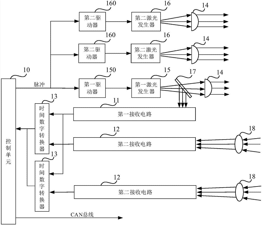
[0034] figure 1 It is a block diagram of a laser radar according to an exemplary embodiment. like figure 1 As shown, the lidar includes a first receiving circuit 11 , a second receiving circuit 12 , a control unit 10 , a first laser generator 15 , a beam splitter 17 and at least one second laser generator 16 .

[0035] The first laser generator 15 is used to emit a first laser beam....


PUM


Abstract

The invention discloses a laser radar and a vehicle. The laser radar comprises a control unit, a first receiving circuit, a second receiving circuit, a first laser generator, a light splitter, and atleast one second laser generator. The first laser generator is used for transmitting a first laser beam. The light splitter is sued for splitting the first laser beam into a reference beam and a firstranging beam, sending the reference beam to the first receiving circuit, and transmitting the first ranging beam to a measured object. The at least one second laser generator is used for transmittinga second ranging beam to the measured object. The first receiving circuit is configured to convert the reference beam into a first electric signal; the second receiving circuit is configured to convert the first ranging beam or the second ranging beam that is reflected by the measured object into a second electric signal; and the control unit calculates a distance between the laser radar and themeasured object based on a time difference between the received first electric signal and second electric signal. Therefore, a technical problem of short detection distance of the related multi-azimuth ranging radar is solved.

Description

technical field [0001] The present disclosure relates to the field of radar ranging, and in particular, to a laser radar and a vehicle. Background technique [0002] In related technologies, the main methods of low-cost vehicle-mounted lidar to realize three-direction measurement include: using a beam-splitting optical lens to split a single laser beam into three laser beams to realize three-direction measurement. The three laser beams are projected in different directions forward according to the decomposition angle of the beam splitting lens, so as to realize the measurement of three azimuth angles and improve the detection range. [0003] The technical shortcomings of the above-mentioned existing low-cost vehicle-mounted lidar that realizes three orientations mainly include: the projection distance is limited, generally more than ten meters away. The reason for the short ranging distance is that after a single laser beam is divided into three beams by the beam splitter o...

Claims


Application Information

Patent Timeline
Patent Type & Authority Applications(China)
IPC IPC(8): G01S7/481
CPCG01S7/4815
Inventor 农英雄
Owner BYD CO LTD
Why Eureka
Try Eureka