
Magnetron

A technology of magnetron and fins, applied in the field of magnetron, can solve the problem of increasing the accommodation space of magnetron

Active Publication Date: 2018-04-06
HIATACHI POWER SOLUTIONS CO LTD
View PDF4 Cites 5 Cited by
  • Summary
  • Abstract
  • Description
  • Claims
  • Application Information

AI Technical Summary

Problems solved by technology

However, the increase in cooling capacity involves an increase in the size of the magnetron, which leads to an increase in the housing space of the magnetron and an increase in the size of the device itself. Therefore, a small magnetron with a cooling structure with excellent performance is required.

Method used


Image

  • Magnetron
  • Magnetron
  • Magnetron

Examples


Deformed example 1

[0067] Such as Figure 9 As shown, the magnetron 200A of Modification 1 includes a cylindrical anode body 211 and a plurality of plate-shaped fins 221A, 222A arranged radially around the central axis 10 of the anode body 211 .

[0068] The plate-shaped fins 221A and 222A are formed with a coolant flow path 223A (communication path, fin inner flow path) through which a coolant passes. The coolant flow path 223A has a U-shape in cross-sectional view, and its opening communicates with the coolant flow paths 212 and 213 of the anode cylinder 211 . Such as Figure 9 As shown, the coolant channel 223A is arranged along the three sides of the plate fins 221A and 222A up to the vicinity of the corner.

[0069] The coolant channel 223A can be produced as follows. For example, the horizontal communication holes 223A are bored (cut) in parallel from the top and bottom of the end faces of the plate fins 221A and 222A (joint end faces on the fixed side of the inner peripheral portion of...

Deformed example 2

[0077] Such as Figure 10 As shown, the magnetron 200B of Modification 2 includes a cylindrical anode body 211 and a plurality of plate-shaped fins 221B, 222B arranged radially around the central axis 10 of the anode body 211 .

[0078] The plate-shaped fins 221B and 222B are formed with a coolant flow path 223B (communication path, fin inner flow path) through which a coolant passes inside. The coolant flow path 223B has a V-shape in cross-sectional view, and its opening communicates with the coolant flow paths 212 and 213 of the anode cylinder 211 . The coolant flow paths 223B are inclined in directions away from the opposing upper and lower sides of the plate-shaped fins 221B, 222B, respectively, and cross each other inside.

[0079] The coolant channel 223B can be fabricated as follows. For example, from the top and bottom of the end faces of the plate-shaped fins 221B and 222B (the end face on the fixed side of the inner peripheral portion of the anode cylinder 211 ), a...


PUM


Abstract

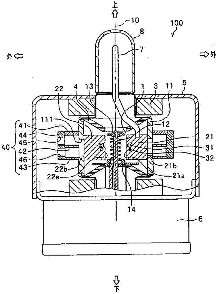
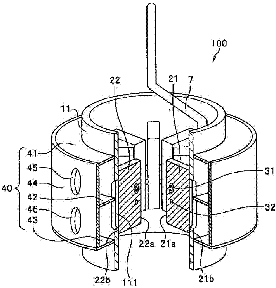
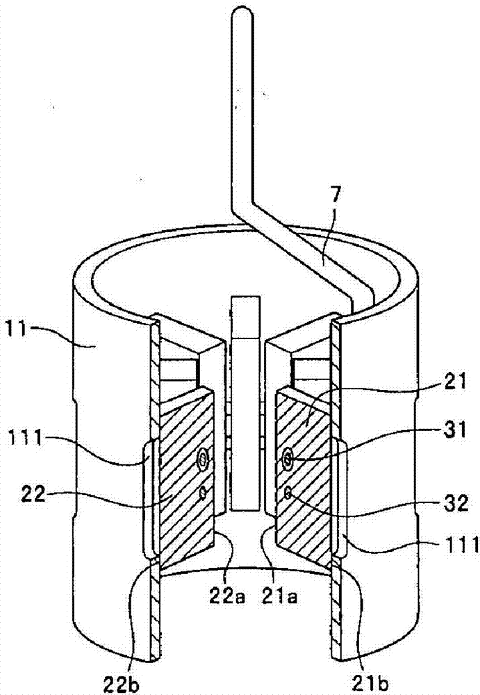
A magnetron includes an anode cylinder extending in a cylindrical shape along a central axis and a plurality of plate-like vanes at least each one end of which is fixed to the anode cylinder, extending from an inner face of the anode cylinder toward the central axis, in which the anode cylinder includes refrigerant flow paths for directly applying a refrigerant to the plate-like vanes. The refrigerant flow paths 111 are openings formed so that end surfaces (joint end faces of the plate-like vanes) of the plate-like vanes are exposed, which allow the refrigerant to directly contact the plate-like vanes.

Description

technical field [0001] The present invention relates to magnetrons as electron tubes for generating microwaves. Background technique [0002] In general, magnetrons are widely used in the fields of radar equipment, medical equipment, cookers such as high-frequency electronic food heaters, semiconductor manufacturing equipment, and other microwave-applied equipment because they can efficiently generate high-frequency output. High-output microwaves are required for use in semiconductor devices or industrial heating. In this case, it is necessary to improve the cooling performance of the magnetron according to the output of the microwave, and it is necessary to enlarge the cooling capacity. However, an increase in cooling capacity involves an increase in the size of the magnetron, resulting in an increase in the housing space for the magnetron and an increase in the size of the device itself. Therefore, a small magnetron with an excellent cooling structure is required. [000...

Claims


Application Information

Patent Timeline
Patent Type & Authority Applications(China)
IPC IPC(8): H01J23/033H01J25/50
CPCH01J23/033H01J25/50H01J23/005H01J23/20H01F27/025H01F27/10
Inventor 神山健太郎虎井礼司
Owner HIATACHI POWER SOLUTIONS CO LTD
Learn More