Vehicle Array Radar Antenna and Lights

An array radar and vehicle-mounted technology, which is applied in the field of vehicle-mounted array radar antennas and vehicle lights, can solve the problems of large volume, inconvenient installation, and small reflection coefficient of the back focus antenna, and achieve the effect of satisfying high gain, simple structure and convenient installation.

Active Publication Date: 2019-02-26
BYD CO LTD
View PDF3 Cites 2 Cited by
  • Summary
  • Abstract
  • Description
  • Claims
  • Application Information

AI Technical Summary

Problems solved by technology

[0003] However, the rear focus antenna in the above-mentioned antenna system is actually a horn antenna. The gain of the horn antenna is relatively high, but the receiving area is small, and the reflection coefficient on its mouth surface is small. The feed source of the sub-radiating back-fed parabolic receiving antenna, and this kind of back-focus antenna is large in size and inconvenient to install, which will increase the volume of the entire antenna system and limit the application environment

Method used


Image

  • Vehicle Array Radar Antenna and Lights
  • Vehicle Array Radar Antenna and Lights
  • Vehicle Array Radar Antenna and Lights

Examples


Embodiment Construction

[0019] Embodiments of the present application are described in detail below, examples of which are shown in the drawings, wherein the same or similar reference numerals denote the same or similar elements or elements having the same or similar functions throughout. The embodiments described below by referring to the figures are exemplary, and are only for explaining the present application, and should not be construed as limiting the present application. On the contrary, the embodiments of the present application include all changes, modifications and equivalents falling within the spirit and scope of the appended claims.

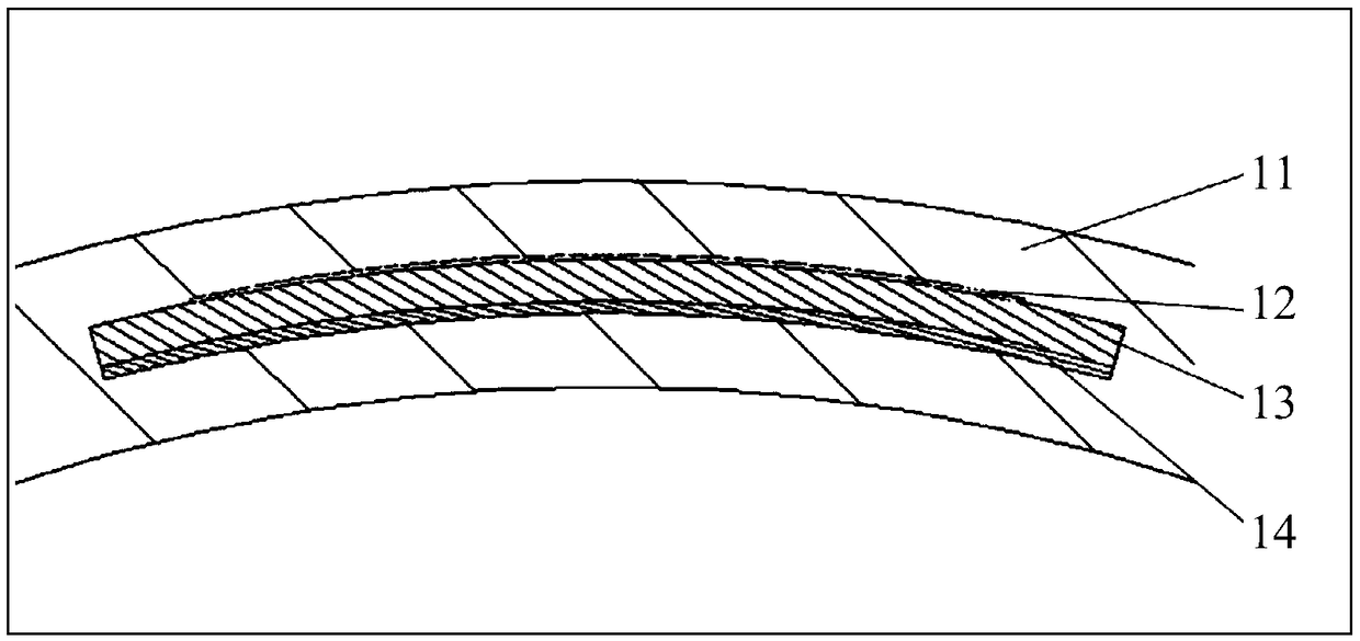
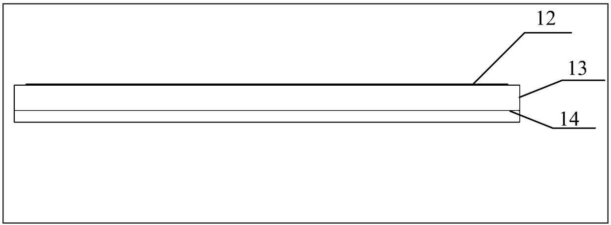
[0020] figure 1 It is a structural schematic diagram of an embodiment of the vehicle-mounted array radar antenna of the present application, such as figure 1 As shown, the vehicle-mounted radar antenna array is embedded in the lampshade 11 of the vehicle lamp, and the vehicle-mounted radar antenna includes a microstrip patch antenna array 12, a dielectric ...


PUM


Abstract

Provided are a vehicle-mounted array radar antenna and a vehicle lamp. The vehicle-mounted array radar antenna is embedded in a shade of a vehicle lamp. The vehicle-mounted array radar antenna comprises a microstrip patch antenna array, a media substrate and a reflecting surface. The microstrip patch antenna array is positioned at and connected to an upper surface of the media substrate. The reflecting surface is positioned under and connected to a lower surface of the media substrate. The vehicle-mounted array radar antenna has a low profile and a simple structure and can be conveniently installed in the shade of the vehicle lamp without needing any additional material. Moreover, the use of a microstrip array antenna satisfies the requirements of high gain and a small angle.

Description

technical field [0001] The present application relates to the technical field of automobile manufacturing, in particular to a vehicle array radar antenna and a vehicle light. Background technique [0002] A vehicle-mounted millimeter wave anti-collision radar antenna system in the prior art includes a rear focus antenna, a lens unit is fixed at the open end of the rear focus antenna, and a microstrip antenna is fixed at the narrow end; the lens unit includes a transmitting lens and The receiving lens, the microstrip antenna includes a transmitting antenna and a receiving antenna, and the receiving antenna irradiates the receiving lens through three microstrip patch feeds parallel in the horizontal direction; the above-mentioned transmitting antenna is connected with a power amplifier, a directional coupler, a voltage-controlled oscillator and The linear modulator and the receiving antenna are sequentially connected with a low-noise amplifier, a low-pass filter and an interme...

Claims


Application Information

Patent Timeline
Patent Type & Authority Patents(China)
IPC IPC(8): H01Q1/32F21V33/00
CPCF21V33/00H01Q1/3208H01Q1/3291
Inventor 吕姝慧王文松王发平
Owner BYD CO LTD
Why Eureka
Try Eureka