
Automatic busbar wire welding system

An automatic welding and wire technology, applied in welding equipment, auxiliary welding equipment, welding/cutting auxiliary equipment, etc., can solve the problems of high welding defect rate, high rework rate, low production efficiency, etc., achieve high processing efficiency and improve production Efficiency, easy installation and debugging

Inactive Publication Date: 2018-04-10
卢光贤
View PDF0 Cites 2 Cited by
  • Summary
  • Abstract
  • Description
  • Claims
  • Application Information

AI Technical Summary

Problems solved by technology

Due to the large size difference and various shapes and styles of the previous busbar wire, the product welding is difficult, the welding defect rate is high, the production efficiency is low, and the rework rate is high. The existing tooling and clamping cannot meet the general production of all products.

Method used


Image

  • Automatic busbar wire welding system
  • Automatic busbar wire welding system
  • Automatic busbar wire welding system

Examples


Embodiment Construction

[0015] The following will clearly and completely describe the technical solutions in the embodiments of the present invention with reference to the accompanying drawings in the embodiments of the present invention. Obviously, the described embodiments are only some, not all, embodiments of the present invention. Based on the embodiments of the present invention, all other embodiments obtained by persons of ordinary skill in the art without making creative efforts belong to the protection scope of the present invention.

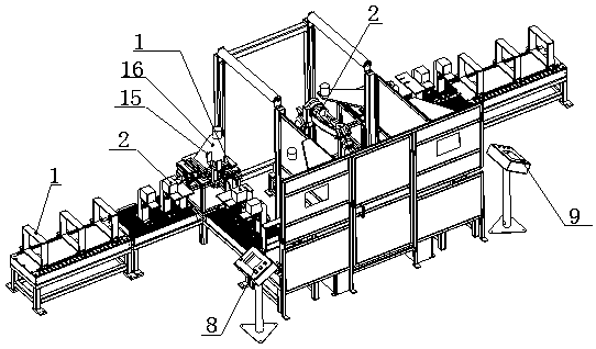
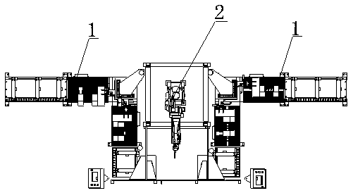
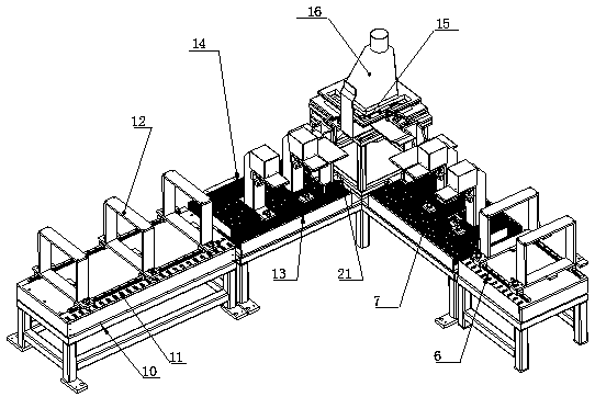
[0016] see Figure 1-3 , in an embodiment of the present invention, an automatic welding system for bus wires includes a station system 1 and a welding robot 2, the station system 1 includes a feeding mechanism 4, a positioning welding mechanism 3 and a discharging mechanism 5, and the feeding mechanism 4 and the discharge mechanism 5 are respectively arranged on the feed inlet side and the discharge outlet side of the positioning welding mechanism 3, and are ...


PUM


Abstract

An automatic welding system for bus wires, including a station system and a welding robot, the station system includes a feeding mechanism, a positioning welding mechanism, and a discharging mechanism, and the feeding mechanism and the discharging mechanism are respectively arranged on the feeding mechanism of the positioning welding mechanism. The mouth side and the discharge port side are placed perpendicularly to each other. The feeding mechanism and the discharging mechanism are composed of a supporting mechanism and a clamping positioning mechanism connected to each other; The station system and the second station system, a welding robot is installed between the first station system and the second station system; Tight positioning, can meet the welding of various shapes of busbar wire products, and adopts double-station alternate work, high processing efficiency.

Description

technical field [0001] The invention relates to the field of busbar wire welding processing, in particular to an automatic busbar wire welding system. Background technique [0002] With the emergence of modern engineering facilities and equipment, the power consumption of all walks of life is increasing rapidly, especially the emergence of many high-rise buildings and large workshops. The traditional cables used as power transmission wires can no longer meet the requirements in large current transmission systems. The parallel use of multiple cables brings a lot of inconvenience to the site installation and construction connection. As a new type of power distribution wire, the plug-in bus duct has emerged at the historic moment. Compared with the traditional cable, it fully demonstrates its superiority in the transmission of large currents. The contact resistance and temperature rise of the joints at both ends of the slot and the connection of the distribution port, and the ...

Claims


Application Information

Patent Timeline
IPC IPC(8): B23K37/00B23K37/02B23K37/04
CPCB23K37/00B23K37/0252B23K37/0443B23K37/0461
Inventor 卢光贤
Owner 卢光贤
Learn More