[0029] In order to clearly illustrate the technical characteristics of this solution, the following describes the solution through specific implementations.
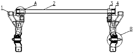
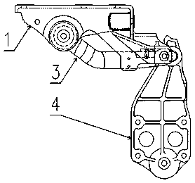
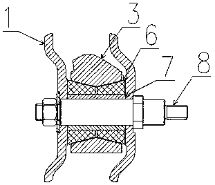
[0030] Such as Figure 1-4 As shown, this embodiment is a front cantilever stabilizer bar device for a heavy truck cab, which includes a front cantilever upper bracket 1, which is mounted on the bottom of the cab, and the front cantilever upper bracket 1 is hinged with a front suspension The front end of the arm 3, the front suspension arm 3 is fixedly connected with a stabilizer bar 2, the front suspension arm 3 and the stabilizer bar 2 are hinged with a front suspension support 4, the front suspension support 4 is assembled to the frame, and the front suspension arm 3 The end is provided with tapered holes on both sides of the hinge joint of the front suspension upper bracket 1, and the tapered holes on both sides are provided with a polyurethane bearing 6 with a conical outer side. The inner hole of the polyurethane bearing 6 is provided with a through front The sleeve 7 at the end of the cantilever arm 3, the inner hole of the sleeve 7 is movably connected with a swing arm pin 8, which is fixedly connected with the upper cantilever support 1; the front suspension support 4 and the front suspension arm 3 and A T-shaped bearing 5 is arranged at the hinge joint of the stabilizer bar 2, and the end of the front suspension arm 3 is provided with a through hole to sleeve the position near the end of the stabilizer bar 2, and the end of the stabilizer bar 2 is hinged with the T-shaped bearing 5 . The T-shaped bearing 5 uses MC nylon with a thickness of 5 mm. The inner side of the tapered hole opposite to the two sides of the hinge joint of the front suspension arm 3 and the front suspension upper bracket 1 is provided with an annular platform. The front suspension arm 3 is in interference fit with the polyurethane bearing 6. The front suspension support 4 and the T-shaped bearing 5 are interference fit. Both ends of the swing arm pin 8 are provided with threads, and are fixedly connected with the outer sides of the wings on both sides of the cantilever upper bracket 1 by nuts, so that the front suspension swing arm 3 is located between the wings on both sides of the cantilever upper bracket 1 and on the cantilever. The bracket 1 is hinged. The wing plate at the hinge joint of the front suspension upper bracket 1 and the front suspension arm 3 is provided with protrusions that are bent to both sides of the frame.
[0031] The material of the stabilizer bar 2 is F45MnVS-GB/T15712-2008, which belongs to non-quenched and tempered steel. This material has the advantage of not requiring heat treatment to meet the mechanical properties, while reducing processing costs; the front suspension arm 3 is forged from high-strength materials Therefore, the structural performance of the front suspension arm 3 is ensured to be stable, and the phenomenon of fracture caused by material defects, cracks or even fracture under long-term force, and deformation after long-term force are avoided, and the reliability and safety of the front suspension device are improved.
[0032] The swing arm of the front suspension arm 3 adopts an elliptical cross-sectional structure, which not only can withstand high-strength loads, but also increases the movement space with other connecting parts to avoid the front suspension arm 3 from being connected to other parts during the movement. Pieces dry grinding phenomenon. The deviation angle of the front and rear ends of the front suspension arm 3 is 18°. This deviation angle increases the lateral distance between the front suspension device and the engine water tank and facilitates the arrangement of the engine water tank. At the same time, the deviation angle improves the ride comfort of the entire vehicle.
[0033] The holes of T-shaped bearing 5 and front suspension support 4 adopt interference fit, front suspension support 4 adopts ø40H7 reference hole, and the outer diameter of T-shaped bearing 5 adopts ø40(+0.15)/(+0.1)mm, this parameter The interference fit not only prevents the T-shaped bearing 5 from loosening and rotating in the hole of the front suspension support 4, but also prevents the T-shaped bearing 5 and the front suspension support hole from having a large interference due to the large interference. Wear. The ends of the T-shaped bearing 5 and the front suspension support 4 are processed with a 25° chamfer, and the chamfer can play a guiding role during the pressing of the T-shaped bearing 5. The inner hole of the T-shaped bearing 5 and the stabilizer bar 2 adopt a clearance fit, and the T-shaped bearing 5 is pressed into the H7 reference hole. The inner diameter tolerance is ø30(+0.1)/0mm, and the shaft end tolerance of the stabilizer bar 2 is ø300/(-0.021) mm, the matching of this parameter not only prevents the stabilizer bar 2 from jumping in the inner hole of the T-bearing 5 due to the excessive clearance, which causes abnormal noise, but also avoids the phenomenon of axle holding caused by the too small clearance, and improves the reliability and safety.
[0034] The polyurethane bearing 6 and the front suspension arm 3 adopt an interference fit, and the interference is 0.8mm. This interference parameter can prevent the polyurethane bearing from rotating in the cone-shaped hole of the front suspension arm, and avoid causing the surface of the polyurethane bearing to wear. The inner side of the tapered hole at the end of the front suspension arm and the two sides of the hinged position of the front suspension upper bracket is provided with a ring platform. The width of the ring platform is 2mm. The width of the platform can accommodate the interference material of the polyurethane bearing to avoid both sides. The squeezing phenomenon of the polyurethane bearing of the polyurethane bearing improves the life of the polyurethane bearing.
[0035] The sleeve 7 and the inner hole of the polyurethane bearing 6 adopt an interference fit. This fit prevents the sleeve from rotating in the inner hole of the polyurethane bearing, causing the inner hole of the polyurethane bearing to wear and abnormal driving noise. The swing arm pin 8 and the inner hole of the sleeve 7 adopt a clearance fit of H9/d9, which prevents abnormal noise when the swing arm pin rotates in the inner hole of the sleeve, improves the reliability and stability of the front suspension, and reduces The processing cost of the swing arm pin and sleeve.
[0036] During the work time:
[0037] The polyurethane bearing 6 and the front suspension arm 3 adopt an interference fit. The front suspension system rotates around the swing arm pin 8 during driving to reduce the wear of the polyurethane bearing 6; the polyurethane bearing 6 is made of polyurethane, which has abrasion resistance and heat resistance Both are better than rubber, improve the service life of the front suspension system, and improve the stability, reliability and safety of the vehicle.
[0038] There is a platform in the tapered hole of the front suspension arm 3, so that grease can be applied here during assembly to provide lubrication and reduce the friction loss between the polyurethane bearing 6 and the sleeve 7 caused by the swing of the front suspension bracket 1 during driving. .
[0039] The T-shaped bearing 5 and the front suspension support 4 have an interference fit to prevent the T-shaped bearing 5 from rotating in the front suspension support hole during driving, causing abnormal noise; the T-shaped bearing 5 is made of MC nylon with a thickness of 5mm. It can withstand high-strength loads, has high wear resistance, self-lubricating, and no abnormal noise.
[0040] The undescribed technical features of the present invention can be achieved through or by using the existing technology, and will not be repeated here. Of course, the above description is not a limitation of the present invention, and the present invention is not limited to the above examples. Those of ordinary skill in the art Changes, modifications, additions or substitutions made within the essential scope of the present invention shall also belong to the protection scope of the present invention.