Eureka AIR delivers breakthrough ideas for toughest innovation challenges, trusted by R&D personnel around the world.

An installation process of prefabricated composite support structure based on section steel

A prefabricated assembly and installation process technology, applied in the installation of bolts, shaft equipment, shaft lining and other directions, can solve the problems of small shrinkage, waste of funds, structural instability, etc., to improve stress conditions, reduce mold costs, Avoid the effect of stress concentration

Active Publication Date: 2019-07-05
SHANDONG JIANZHU UNIV
View PDF6 Cites 0 Cited by
  • Summary
  • Abstract
  • Description
  • Claims
  • Application Information

AI Technical Summary

Problems solved by technology

However, in engineering practice, due to the uneven surface of the surrounding rock of the roadway and the complex stress conditions of the supports, it is easy to form stress concentration or partial load
Under the pressure of the surrounding rock of the roadway, the U-shaped steel bracket often bends and breaks in the plane, or turns and twists outside the plane, and there are many low-resistance breakages caused by structural instability, longitudinal force, and eccentric load roll , so that the bearing capacity of the U-shaped steel bracket cannot be fully utilized
Once the bracket is damaged in the above situation, almost all the bearing capacity will be lost, and the continuous repair in the later period will not only cause a waste of funds, but also cost a lot of time
[0006] To sum up, in the support technology of deep well soft rock roadway, there are mainly problems of low bearing capacity of support structure, high cost, small shrinkage, and continuous repair of roadway

Method used


Image

  • An installation process of prefabricated composite support structure based on section steel
  • An installation process of prefabricated composite support structure based on section steel
  • An installation process of prefabricated composite support structure based on section steel

Examples


Embodiment Construction

[0042] The present invention will be further described below in conjunction with accompanying drawing.

[0043] In order to make the content of the present invention more clearly understood, the present invention will be further described in detail below based on specific embodiments and in conjunction with the accompanying drawings.

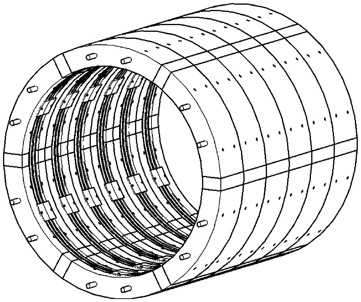
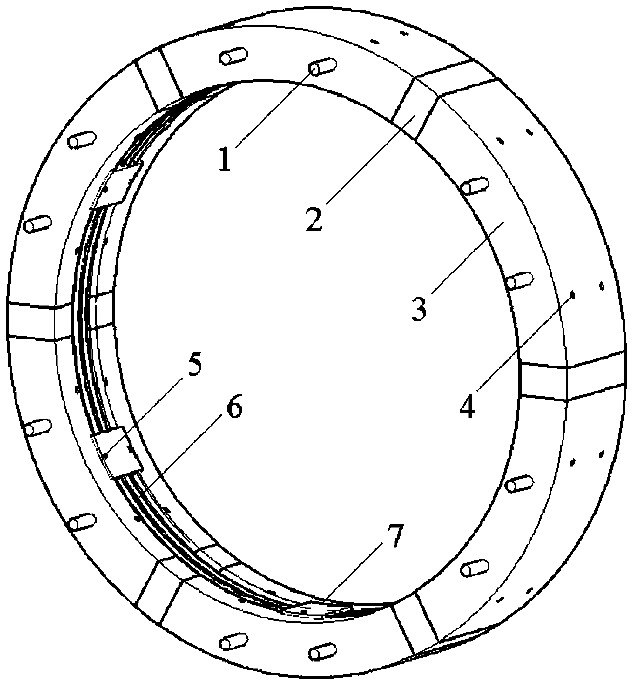
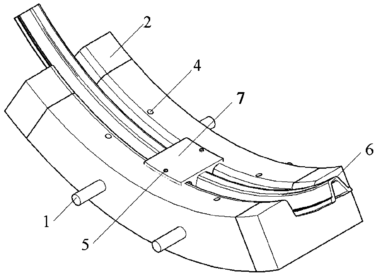
[0044]As shown in the figure, the present invention includes a single-ring support structure, in which steel is embedded in the single-ring support structure, and the structural shape of the single-ring support structure matches the channel profile; a plurality of the single-ring support structures The supporting structures are axially connected along the channel to form the supporting system. Specifically, the single-ring support structure includes a multi-section prefabricated assembly structure 3; multiple sections of the prefabricated assembly structure 3 are assembled together to form the single-ring support structure; a plurality of the si...


PUM


Abstract

The invention relates to an installation technology for a prefabricated type compound support structure based on section steel. The installation technology for the prefabricated type compound supportstructure based on the section steel comprises the following steps that (1), concrete members are hoisted in position, a structure body is anchored on a base plate by anchor rods and / or anchor ropes passing through anchor rod holes or anchor rope holes reserved in the prefabricated type compound support structure; (2), remaining concrete members expect the base plate are installed by a special installation device, and the structure body is anchored on surrounding rock by the anchor rod holes or the anchor rope holes reserved in the structure body after each concrete member is mounted in position; (3), multiple pieces of section steel are embedded into grooves of the concrete members to form a section steel support; (4), connectors of the section steel support are clamped by clamping cables, and the degree of tightness of the clamping cables is adjusted, so that the connectors of the section steel support are staggered with each other to release pressure accumulated in the support, andthe function of pressure relief is finished; and (5), installation of a single ring of the supporting structure is finished, and the steps (1)-(4) are repeated to install the next ring of the supporting structure. According to the installation technology for the prefabricated type compound support structure, structural stability and carrying capacity are enhanced.

Description

technical field [0001] The invention relates to the field of roadway support, in particular to an installation process of a prefabricated assembled composite support structure based on section steel. Background technique [0002] At present, the main support technologies for soft rock roadways in deep wells include: anchor net spray support series technology, section steel support series technology, reinforced concrete structure support series technology and steel pipe concrete support support technology, etc. [0003] With the increase of roadway burial depth, conventional support methods such as simple anchor rods and cables can no longer meet the needs of roadway stability. The roadway needs to be continuously repaired, and the soft rock roadway is severely deformed or even damaged. [0004] Although the concrete-filled steel tube support has a high load-bearing capacity and has achieved good support effects in engineering practice, its high cost has always restricted it...

Claims


Application Information

Patent Timeline
Patent Type & Authority Patents(China)
IPC IPC(8): E21D11/08E21D11/14E21D20/00
CPCE21D11/08E21D11/083E21D11/14E21D20/00
Inventor 王军谢浩左建平顾薛青徐亮宋建新王正泽王波
Owner SHANDONG JIANZHU UNIV
Why Eureka
Eureka Blog
Learn More