

Solenoid valve case
A technology of solenoid valve and solenoid valve assembly, applied in valve details, valve device, valve operation/release device, etc., can solve the problems of difficult installation and arrangement, limited site space, troublesome maintenance, etc., and achieve convenient maintenance, transformation and upgrading , convenient operation and construction, simple maintenance effect
- Summary
- Abstract
- Description
- Claims
- Application Information
AI Technical Summary
Problems solved by technology
Method used
Image


Examples
Embodiment 1
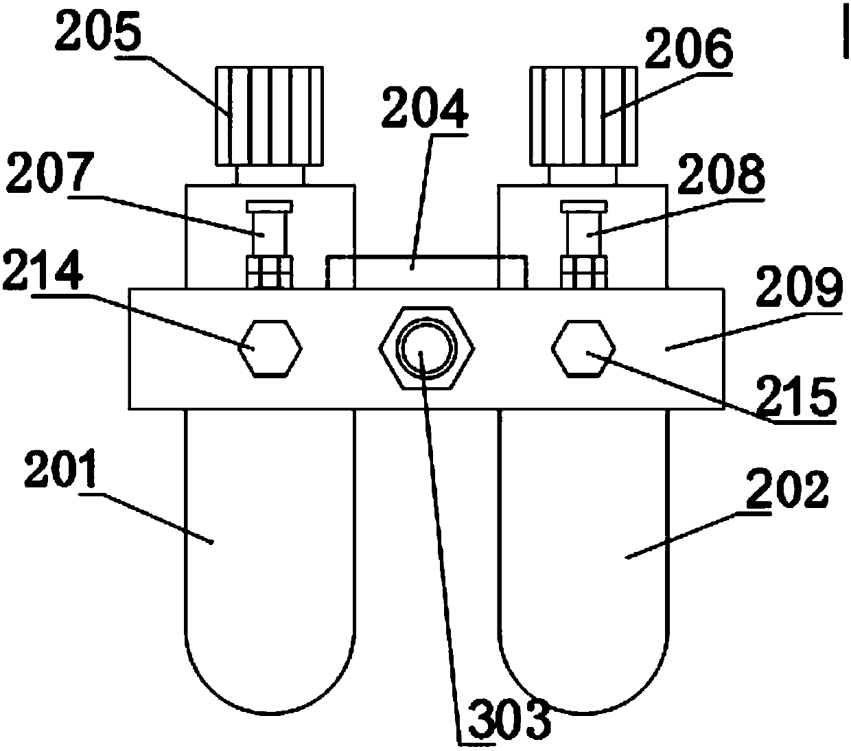
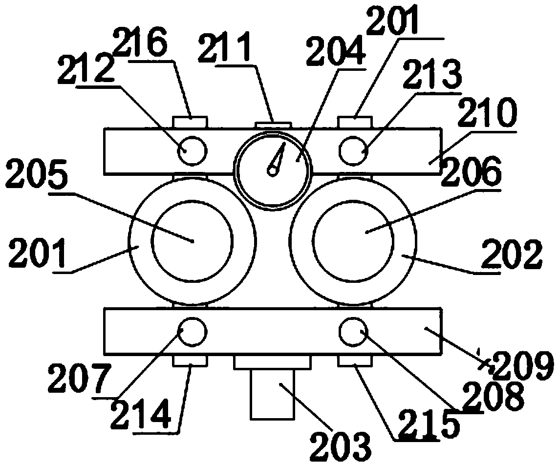
[0030] see figure 1 , figure 2 , image 3 , Figure 4 , Figure 5 , Image 6 , Figure 7 The present embodiment provides a gas dehydration device 108, a filter decompression assembly 102, and a box body 115 that are connected in sequence. A water port 85, an air outlet 82 arranged at the top of the separation cylinder and a gas deflector 83 arranged in the separation cylinder; an air source distributor assembly 104, a solenoid valve assembly 105 are arranged in the box, and the filter decompression assembly 102 It is arranged in communication with the air source distributor assembly 104, and the air source distributor assembly 104 is arranged in communication with the solenoid valve assembly 105. The terminal installation guide rail 110 and the zero connection grounding terminal and the terminal installation guide rail 110 are also provided in the box. A circuit breaker 107, the bottom of the box is provided with a sealed waterproof cable joint 113 and a stainless steel...
Embodiment 2
[0038] see figure 1 , figure 2 , image 3 , Figure 4 , Figure 5 , Image 6 , Figure 7 The present embodiment provides a gas dehydration device 8, a filter decompression assembly 2 and a box body 15 that are connected in sequence. A water port 85, an air outlet 82 arranged on the top of the separation cylinder and a gas deflector 83 arranged in the separation cylinder; the gas source distributor assembly 4 and the solenoid valve assembly 5 are arranged in the box, and the filter decompression assembly 2 It is arranged in communication with the air source distributor assembly 4, and the air source distributor assembly 2 is arranged in communication with the solenoid valve assembly 5. The terminal installation guide rail 10 and the zero-connection grounding terminal and the terminal installation guide rail 10 are also provided in the box. A circuit breaker 7, the bottom of the box is provided with a sealed waterproof cable joint 13 and a stainless steel through-board jo...
PUM
 Abstract
Description
Claims
Application Information