Automatic turning mechanism used for nursing bed

An automatic turning and nursing bed technology, which is applied in the fields of hospital beds, vehicle rescue, medical science, etc., can solve the problems of being unable to help patients, automatic turning over, and difficulty turning over, so as to help the recovery of the disease, improve the quality of use, The effect of turning over is safe and stable

Active Publication Date: 2018-04-13
NORTH CHINA UNIVERSITY OF SCIENCE AND TECHNOLOGY
View PDF9 Cites 2 Cited by
  • Summary
  • Abstract
  • Description
  • Claims
  • Application Information

AI Technical Summary

Problems solved by technology

[0003] The existing nursing beds have a simple structure and relatively simple performance. They cannot help patients to turn over automatically during medical care. For some patients with serious conditions, turning over is difficult and easily involves the wound, which is not conducive to the recovery of the disease.
Therefore, the published application number is 201710191623.5, which proposes an automatic turning mechanism applied to nursing beds. It mainly wants to solve the problem of occupying space when the nursing bed turns over, and uses the motor to drive the rotating plate of the square frame to rotate, and finally realizes the turning of the bed. Purpose, the stability of this rotation method is poor
The patient's body does not have a good point of focus, accidents are prone to occur during the turning process, and there are certain limitations in actual operation

Method used


Image

  • Automatic turning mechanism used for nursing bed
  • Automatic turning mechanism used for nursing bed
  • Automatic turning mechanism used for nursing bed

Examples


Embodiment

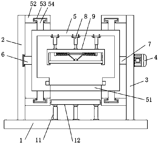
[0026] refer to Figure 1-4 , an automatic turning mechanism applied to a nursing bed, comprising a base plate 1, an automatic turning mechanism arranged on the top of the bottom plate 1, and a bed plate lifting mechanism located in the middle of the automatic turning mechanism;

[0027] The automatic turning mechanism includes a first support plate 2 and a second support plate 3 welded on both sides of the top of the bottom plate 1, and a motor 4 is installed on the outer end surface of the second support plate 3, and the first support plate 2 and the second support plate 3 There is an overturn bracket 5, and the motor 4 drives the overturn bracket 5 to rotate axially;

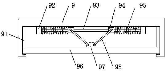
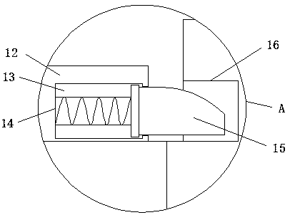
[0028] The bottom of the overturn bracket 5 is provided with an active port 51 corresponding to the bed board lifting mechanism, and the inside of the overturn bracket 5 is provided with an elastic docking mechanism, which includes the docking bracket 9 and the first hydraulic cylinder 8 that drives the docki...


PUM


Abstract

The invention discloses an automatic turning mechanism used for a nursing bed. The automatic turning mechanism comprises a bottom plate and further comprises an automatic turning mechanism body and abed board lifting mechanism, wherein the automatic turning mechanism body is arranged at the top of the bottom plate, and the bed board lifting mechanism is located in the middle of the automatic turning mechanism body; the automatic turning mechanism body comprises a first supporting plate and a second supporting plate, wherein the first supporting plate and the second supporting plate are weldedto the two sides of the bottom of the bottom plate, a motor is installed on the outer end face of the second supporting plate, a turning support is arranged between the first supporting plate and thesecond supporting plate, and the motor drives the turning support to rotate in the axial direction; a moving opening is formed in the bottom of the turning support and corresponds to the bed board lifting mechanism, an elastic butt joint mechanism is arranged inside the turning support and comprises a butt joint support and a first hydraulic cylinder driving the butt joint support to move in thevertical direction, and strip-shaped sliding grooves are formed in the inner walls of the two sides of the butt joint support respectively. The automatic turning mechanism is reasonable in design layout, achieves the purpose of automatic turning, makes turning safe and stable, helps a patient to recover, and improves the comfort degree for the patient and the using quality of the nursing bed.

Description

technical field [0001] The invention relates to the technical field of medical equipment, in particular to an automatic turning mechanism applied to a nursing bed. Background technique [0002] Nursing beds are divided into electric and manual, and are used by patients with limited mobility during hospitalization or home care. Manual is suitable for the short-term nursing needs of patients, and solves a difficult nursing problem in the short term. Electric is suitable for families with long-term bedridden patients with inconvenient mobility. This not only greatly reduces the burden on nursing staff and family members, but most importantly, patients can operate and control their own lives, which greatly improves their confidence in life. A person's needs have also achieved self-satisfaction in terms of quality of life, which is conducive to the recovery of the patient's disease. [0003] The existing nursing beds have a simple structure and single performance, and cannot he...

Claims


Application Information

Patent Timeline
Patent Type & Authority Applications(China)
IPC IPC(8): A61G7/057
CPCA61G7/001A61G7/05A61G2203/70Y02A50/30
Inventor 汪凤兰张执超张小丽邢凤梅董伟芹杨坤
Owner NORTH CHINA UNIVERSITY OF SCIENCE AND TECHNOLOGY
Why Eureka
Try Eureka