

Gas cleaning tank
A gas cleaning and tank technology, which is applied in the directions of using liquid separation agents, dispersed particle separation, chemical instruments and methods, etc., can solve problems such as polluting the environment and harming human health, and achieves increased contact area, extended time, and cleaning effects. Good results
Active Publication Date: 2018-04-13
宁波江北清纬环保科技有限公司
View PDF6 Cites 6 Cited by
- Summary
- Abstract
- Description
- Claims
- Application Information
AI Technical Summary
Problems solved by technology
But when filtering, some solid particles with smaller particle size are difficult to be filtered out. When the waste gas is passed into the solution, the waste gas forms bubbles, and the waste gas in the bubbles is difficult to contact with the reagents in the solution, so the toxic and harmful The gas is difficult to remove, and the exhaust gas after cleaning still contains toxic and harmful gases, which will still pollute the environment and harm human health
Method used
View moreImage
Smart ImageViewing Examples

Examples
Embodiment Construction
[0021] Below in conjunction with accompanying drawing and specific embodiment the present invention will be described in further detail:
Login to View More PUM
 Abstract
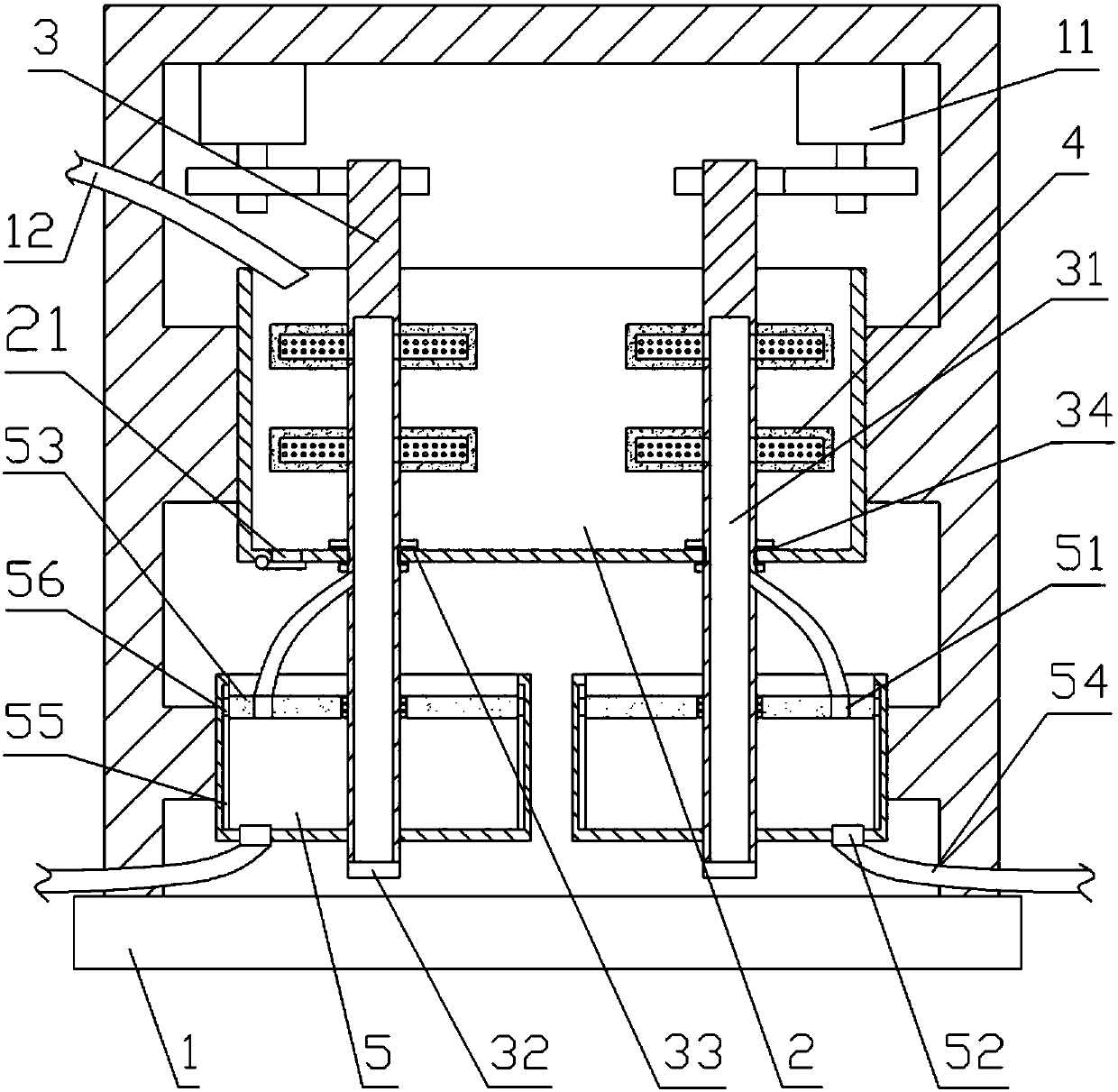
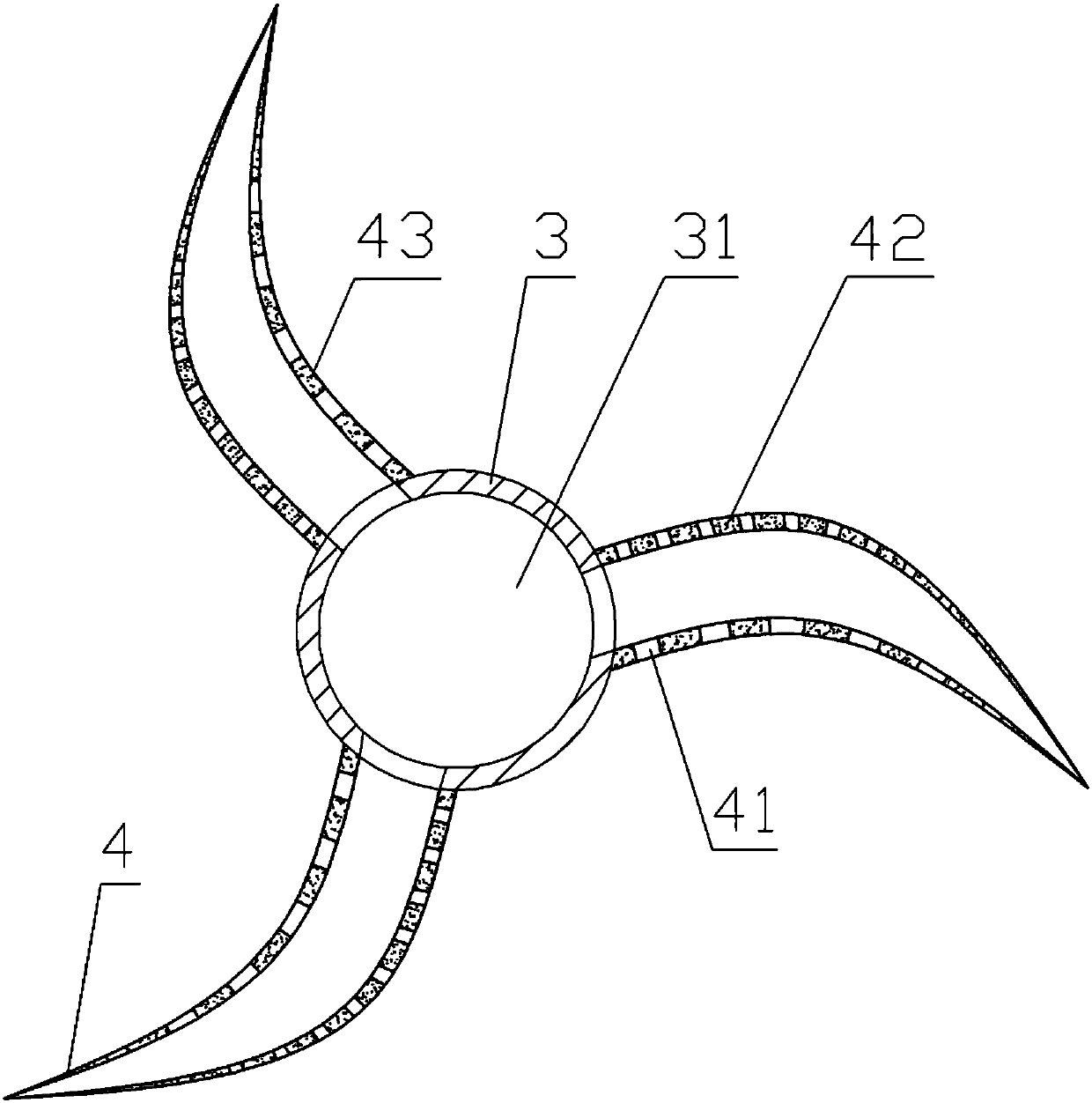
The invention relates to the field of environment protection equipment and discloses a gas cleaning tank which comprises a rack, a stirring mechanism and a tank body, wherein a liquid outlet is formedin the bottom of the tank body; the stirring mechanism comprises a stirring shaft, fan blades, an air inlet cylinder and a stepper motor; a piston is arranged inside the air inlet cylinder; an air inlet tube is fixed on the air inlet cylinder; a cavity is formed in the stirring shaft; an air outlet one-way valve and an air inlet one-way valve are fixed on the side wall of the piston or the air inlet cylinder; the stirring shaft penetrates through the tank body, the piston and the air inlet cylinder; the stirring shaft is in threaded connection with the piston; a plurality of beads are arranged between the stirring shaft and the piston; a chute is formed in the side wall of the air inlet cylinder; a sliding block is fixed on the side wall of the piston; a water outlet is formed in the lower end of the stirring shaft; the fan blades are fixed on the stirring shaft; and through holes are formed in the fan blades. By adopting the gas cleaning tank, the sizes of bubbles can be reduced, andthe contact areas of the bubbles with a solution are increased.
Description
technical field [0001] The invention relates to the field of environmental protection equipment, in particular to a gas cleaning device. Background technique [0002] The current factories will generate waste gas during the production process. These waste gases contain a large amount of toxic and harmful gases and solid particles of different sizes. If the waste gas is discharged directly, the toxic and harmful gases in the waste gas will pollute the environment, and the solid particles are likely to cause smog. It will greatly damage people's health, so it is necessary to purify the exhaust gas before discharging it. [0003] The traditional purification method is to filter the gas to remove solid particles with relatively large particle size and volume in the waste gas; then add the reagent to water to form a solution, and pass the waste gas into the solution, the toxic and harmful gas contacts the solution and reacts with the reagent, so Toxic and harmful gases in exhaus...
Claims
Login to View More Application Information
Patent Timeline
 IPC IPC(8): B01D53/78B01D47/02
Inventor王健
Owner宁波江北清纬环保科技有限公司