Wheat grinding device for food processing
A technology of food processing and wheat, which is applied in the direction of grain processing, etc., can solve the problems of cumbersome operation, insufficient grinding and low work efficiency, and achieve the effect of simple operation, high work efficiency and comprehensive grinding
- Summary
- Abstract
- Description
- Claims
- Application Information
AI Technical Summary
Problems solved by technology
Method used
Image
Examples
Embodiment 1
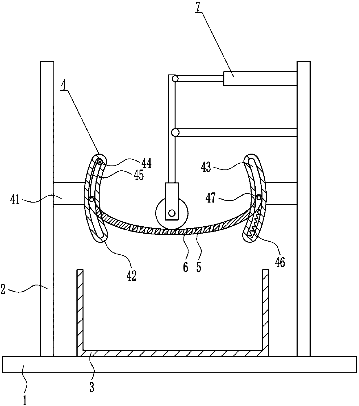
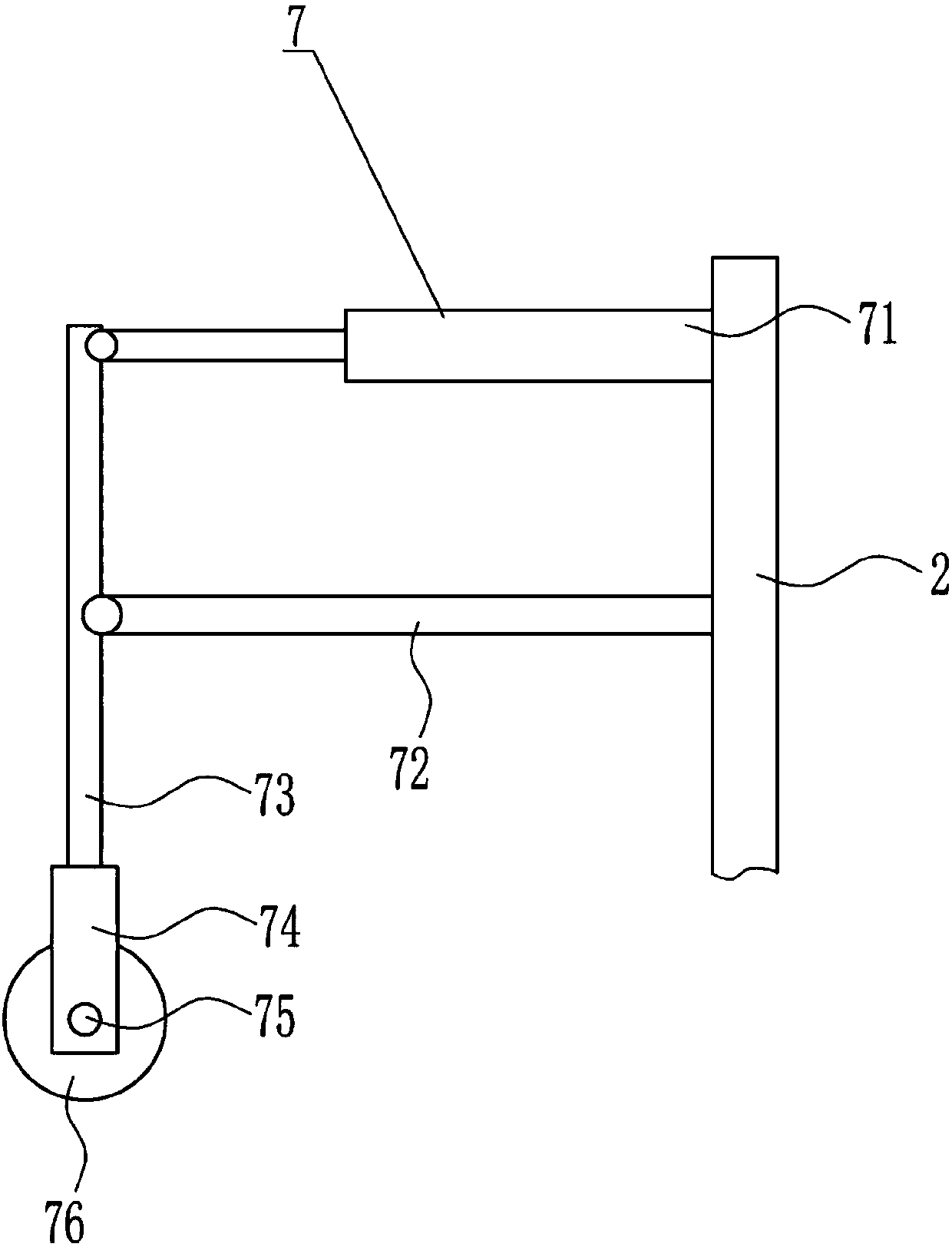
[0038] see figure 1 , a wheat grinding equipment for food processing, such as Figure 1-9 As shown, it includes a bottom plate 1, a support 2, a collection frame 3, a swing device 4, a loading plate 5 and a grinding device 7. The top of the bottom plate 1 is vertically installed with a support 2 symmetrically connected by bolts, and between the two supports 2 A collection frame 3 is installed on the top of the bottom plate 1 through bolt connection, and a swing device 4 is provided in the middle between the two brackets 2. The swing part of the swing device 4 is connected with a loading plate 5, and the openings on the loading plate 5 are evenly spaced. There is a discharge hole 6, the loading plate 5 is located directly above the collection frame 3, and a grinding device 7 is arranged on the upper left side of the right support 2, and the grinding parts of the grinding device 7 are in contact with the top of the loading plate 5.
[0039] Preferably, the swing device 4 includes...
Embodiment 2
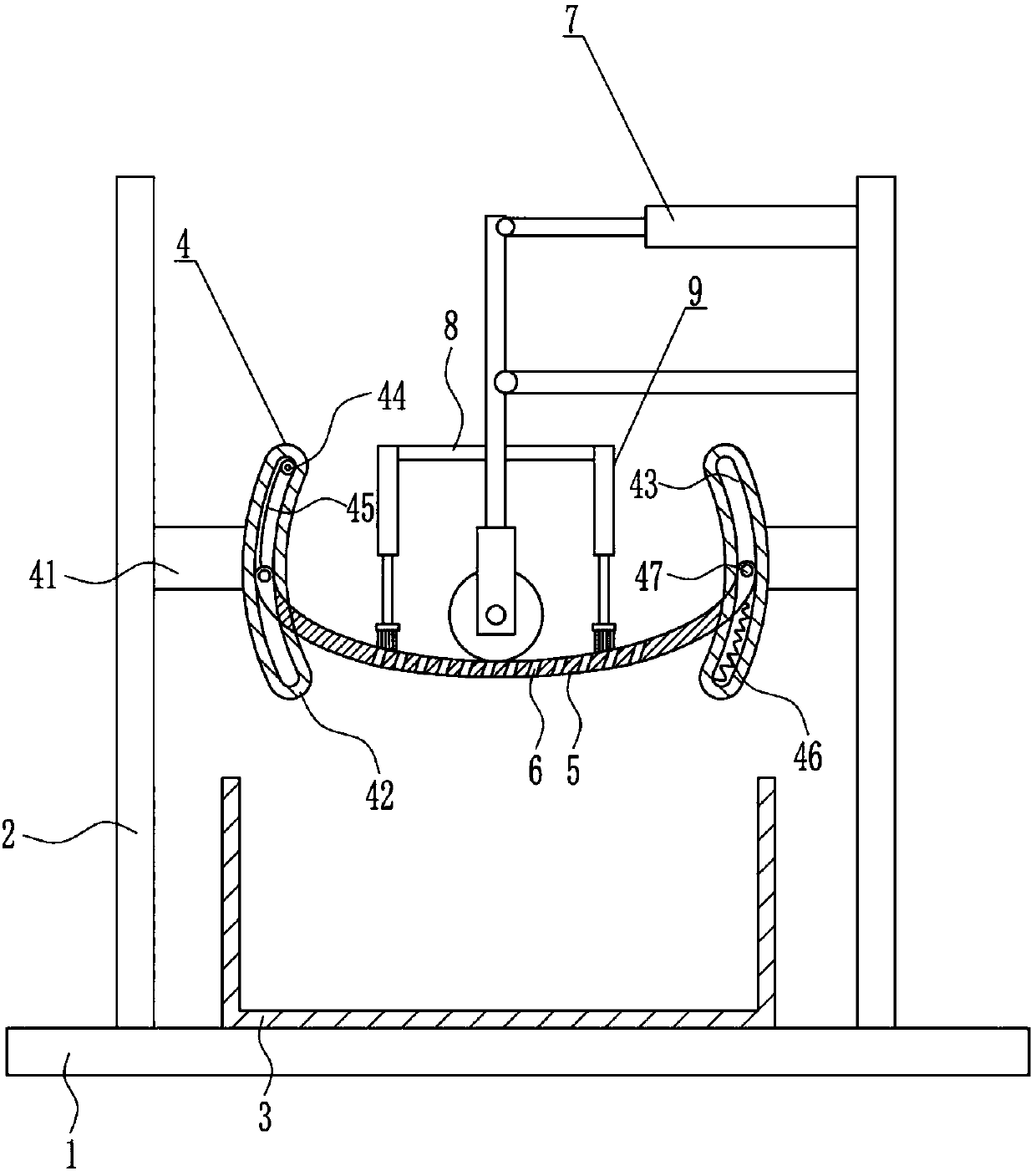
[0042] see image 3 and Figure 4 , different from Embodiment 1, it also includes a connecting rod 8 and a sweeping device 9, the lower parts of the left and right sides of the vertical rod 73 are horizontally connected with the connecting rod 8 by means of bolts, and the outer end of the connecting rod 8 is provided with a sweeping device. Material device 9, material sweeping device 9 comprises sleeve 91, telescoping rod 92, second spring 93 and hairbrush 94, and connecting rod 8 outer end is vertically installed with sleeve 91 by the mode of bolt connection, and sleeve 91 is vertically installed. A telescopic rod 92 is directly provided, and the telescopic rod 92 is slidably matched with the sleeve 91. A second spring 93 is connected between the bottom end of the telescopic rod 92 and the inner top of the sleeve 91. The bottom end of the telescopic rod 92 is connected with a hairbrush 94, and the hairbrush 94 is in contact with the top of the carrier plate 5 .
Embodiment 3
[0044] see Figure 5 and Figure 6 , is different from Embodiment 2 in that it also includes a vibrating device 10. The vibrating device 10 includes a housing 101, an electric cam 102, a movable plate 103, a third spring 104 and a rubber ball 105, and the left side of the collection frame 3 is passed through a bolt The mode of connection is equipped with housing 101, and electric cam 102 is installed in the middle part of the left side in housing 101, and movable plate 103 is vertically provided with in the housing 101 on the right side of electric cam 102, and the upper and lower sides of movable plate 103 left side The third spring 104 is connected between the upper and lower sides of the left side in the side and the housing 101, and a rubber ball 105 is installed in the middle part of the right side of the movable plate 103, and the rubber ball 105 is located on the left side of the collection frame 3.
[0045] Preferably, see Figure 9 , also includes a slide rail 15 an...
PUM
 Abstract
Description
Claims
Application Information
 - R&D
- Intellectual Property
- Life Sciences
- Materials
- Tech Scout
- Unparalleled Data Quality
- Higher Quality Content
- 60% Fewer Hallucinations
Browse by: Latest US Patents, China's latest patents, Technical Efficacy Thesaurus, Application Domain, Technology Topic, Popular Technical Reports.
© 2025 PatSnap. All rights reserved.Legal|Privacy policy|Modern Slavery Act Transparency Statement|Sitemap|About US| Contact US: help@patsnap.com


