
Automatic feeding and discharging mechanical arm of punching machine

An automatic loading and unloading, manipulator technology, applied in metal processing equipment, feeding devices, manufacturing tools, etc., can solve the problems of inability to quickly complete the equipment in place and put into production, troublesome dynamic adjustment of equipment, and inability to manufacture flexibly, and achieve the efficiency of loading and unloading. High, easy to operate, easy to maintain

Active Publication Date: 2018-04-13
绵阳海迪机器人科技有限公司
View PDF7 Cites 15 Cited by
  • Summary
  • Abstract
  • Description
  • Claims
  • Application Information

AI Technical Summary

Problems solved by technology

[0003] However, although this type of robot can solve the problem of automatic loading and unloading of workpieces, it also has many shortcomings: First, the dynamic adjustment of the equipment is troublesome. When using the equipment, it must be required that the punches must be arranged at standard intervals within the stroke range of the manipulator, which cannot Flexible manufacturing, that is, for different plant equipment layouts and different product types, it is impossible to quickly complete the equipment in place and put into production; and it covers too much area and is difficult to maintain

Method used


Image

  • Automatic feeding and discharging mechanical arm of punching machine
  • Automatic feeding and discharging mechanical arm of punching machine
  • Automatic feeding and discharging mechanical arm of punching machine

Examples


Embodiment Construction

[0035]In order to make the purpose, technical solutions and advantages of the embodiments of the present invention clearer, the technical solutions in the embodiments of the present invention will be clearly and completely described below in conjunction with the drawings in the embodiments of the present invention. Obviously, the described embodiments It is a part of embodiments of the present invention, but not all embodiments. The components of the embodiments of the invention generally described and illustrated in the figures herein may be arranged and designed in a variety of different configurations.

[0036] Accordingly, the following detailed description of the embodiments of the invention provided in the accompanying drawings is not intended to limit the scope of the claimed invention, but merely represents selected embodiments of the invention. Based on the embodiments of the present invention, all other embodiments obtained by persons of ordinary skill in the art wit...


PUM


Abstract

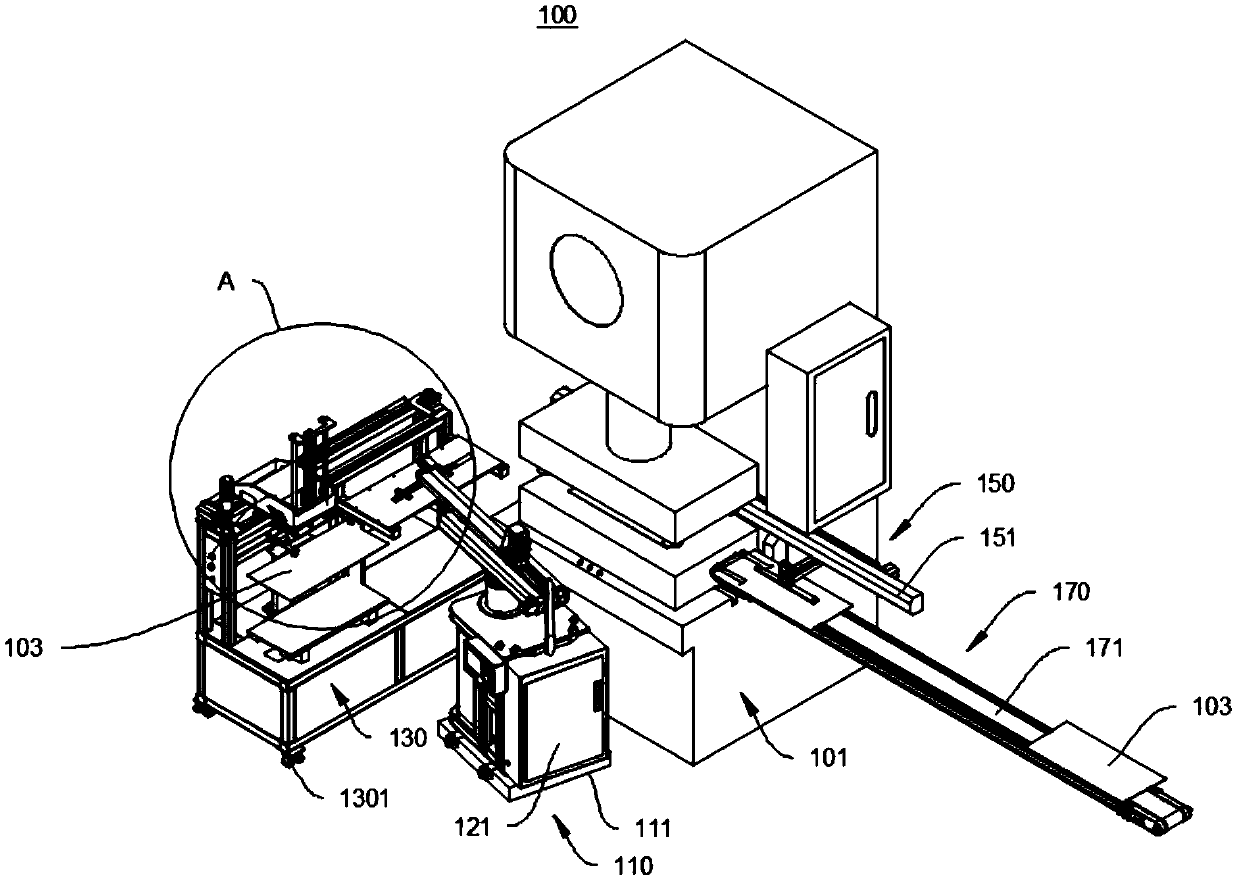
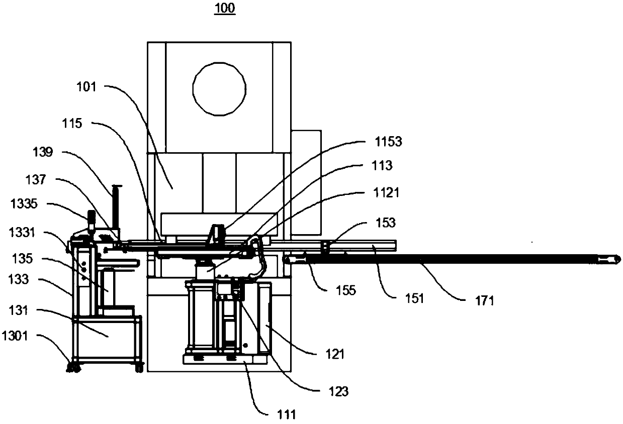
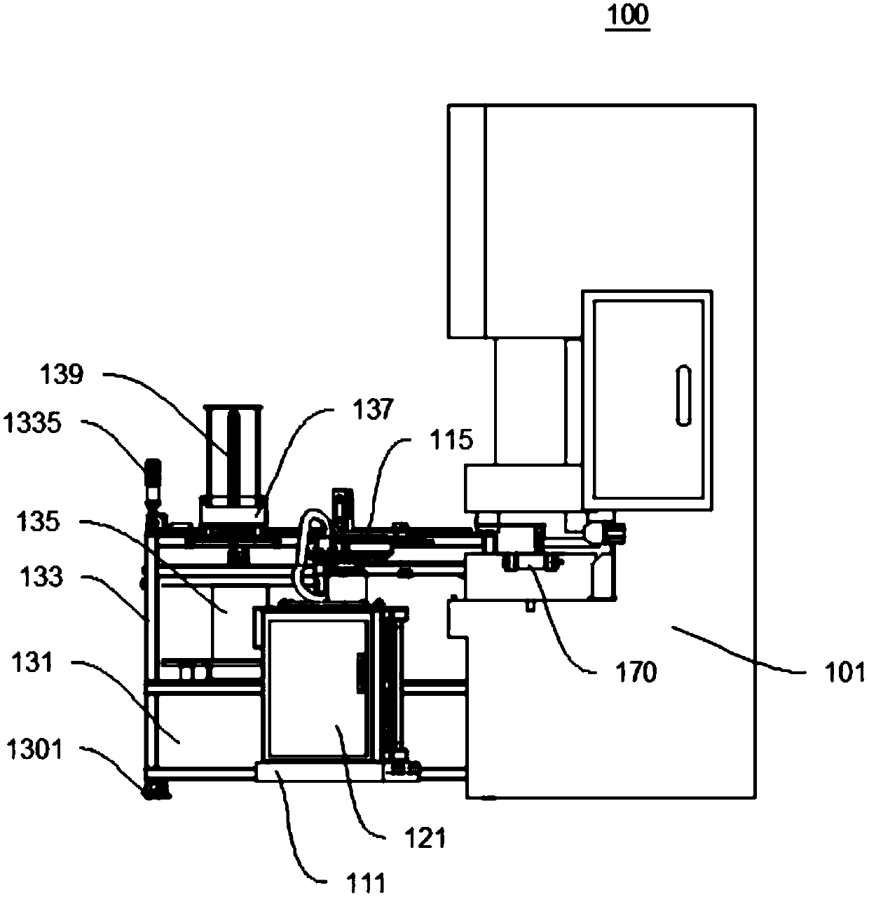
The invention provides an automatic feeding and discharging mechanical arm of a punching machine and relates to the technical field of mechanical automation. The automatic feeding and discharging mechanical arm of the punching machine comprises a feeding platform, a feeding mechanical arm and a horizontal auxiliary arm. The feeding mechanical arm body conveys a product to a punching platform. Thehorizontal auxiliary arm moves the product out from the punching platform. The feeding mechanical arm comprises a first operation platform, a servo motion module, a control system, a manipulator arm and a manipulator hand, wherein the servo motion module, the control system, the manipulator arm and the manipulator hand are installed on the first operation platform. The servo motion module is electrically connected with the control system. The servo motion module is connected with the manipulator arm. The manipulator arm is connected with the manipulator hand. The horizontal auxiliary arm comprises a horizontal beam, a first transmission assembly, a support and a grabbing assembly. The horizontal beam is installed on the punching platform. The first transmission assembly is installed on thehorizontal beam. The support is connected with the first transmission assembly. The grabbing assembly is connected with the support. The automatic feeding and discharging mechanical arm of the punching machine is convenient to manipulate, high in feeding and discharging efficiency, high in control precision, safe and reliable.

Description

technical field [0001] The invention relates to the technical field of mechanical automation, in particular to an automatic loading and unloading manipulator for punching machines. Background technique [0002] The handling and transfer of metal sheet materials has always been a problem in the sheet metal stamping processing industry. The existing stamping automatic loading and unloading manipulators that are commonly used mostly use field three-axis robots to carry out sheet metal handling within the space. The sheet is placed into the die table of the punch press for positioning. [0003] However, although this type of robot can solve the problem of automatic loading and unloading of workpieces, it also has many shortcomings: First, the dynamic adjustment of the equipment is troublesome. When using the equipment, it must be required that the punches must be arranged at standard intervals within the stroke range of the manipulator, which cannot Flexible manufacturing, that...

Claims


Application Information

Patent Timeline
Patent Type & Authority Applications(China)
IPC IPC(8): B21D43/10B21D45/02B21D43/18B21D43/00
Inventor 何坤
Owner 绵阳海迪机器人科技有限公司
Learn More