Welding method

A technology of welding method and welding parameters, which is applied in the field of welding and pipeline welding, and can solve the problems of high welding cost, low welding efficiency, cumbersome welding process, etc.

Active Publication Date: 2018-04-13
HUBEI SANJIANG AEROSPACE GRP HONGYANG ELECTROMECHANICAL
View PDF8 Cites 5 Cited by
  • Summary
  • Abstract
  • Description
  • Claims
  • Application Information

AI Technical Summary

Problems solved by technology

[0005] Aiming at the problems existing in the prior art, the embodiment of the present invention provides a welding method, which is used to solve the techni...

Method used


Image

  • Welding method
  • Welding method
  • Welding method

Examples


Embodiment 1

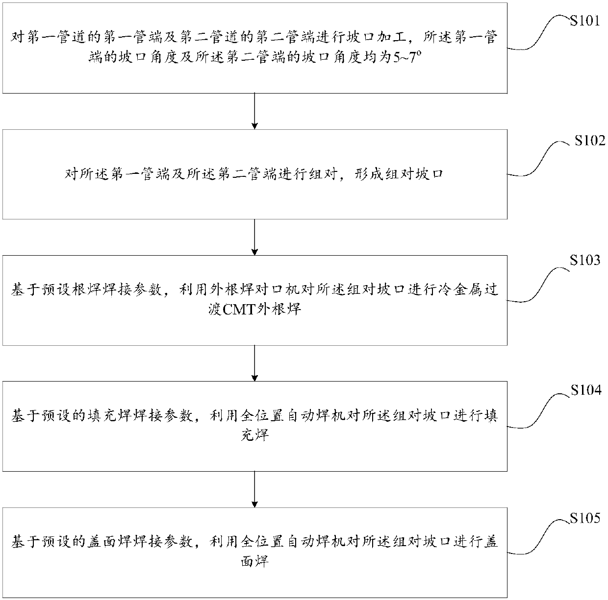
[0036] This embodiment provides a welding method, such as figure 1 As shown, the method includes:

[0037] S101, performing bevel processing on the first pipe end of the first pipeline and the second pipe end of the second pipeline, the bevel angle of the first pipe end and the bevel angle of the second pipe end are both 5-7° .

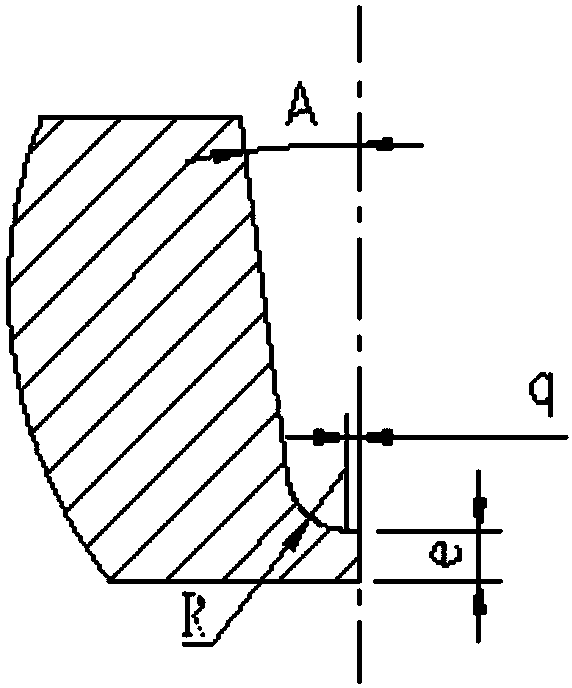
[0038] In this step, before welding the first pipe 1 and the second pipe 2, in order to ensure that the blunt edge of the groove is penetrated and the backside forming effect is ensured, it is necessary to weld the first pipe end of the first pipe 1 and the second pipe 2 Beveling the second pipe end, see figure 2 , the figure 2 Taking the bevel of the first pipe end as an example for illustration, the bevel angle of the first pipe end and the bevel angle of the second pipe end are both 5-7°; the bevel arc radius of the first pipe end is R and the arc radius of the groove of the second pipe end are both 2.4 mm. The groove wall of the first port ...

Embodiment 2

[0055] In practical application, when using the method provided in Embodiment 1 to weld a long oil and gas pipeline, the specific implementation is as follows:

[0056] Before welding the first pipe 1 and the second pipe 2, in order to ensure that the blunt edge of the groove is penetrated and the backside forming effect is ensured, it is necessary to weld the first pipe end of the first pipe 1 and the second pipe of the second pipe 2. end beveling, see figure 2 , the figure 2 Taking the bevel of the first pipe end as an example for illustration, the bevel angle of the first pipe end and the bevel angle of the second pipe end are both 6°; the bevel arc radius R of the first pipe end and The arc radius of the bevel of the second pipe end is 2.4 mm. The groove wall of the first port is tangent to the groove arc of the first pipe end, and the groove wall of the second port is tangent to the groove arc of the second pipe end.

[0057] Moreover, there is a first horizontal tra...


PUM

PropertyMeasurementUnit
Thicknessaaaaaaaaaa

Abstract

The invention provides a welding method. The welding method comprises the following steps: carrying out groove preparation on a first pipe end of a first pipeline and a second pipe end of a second pipeline, wherein the bevel angles of the first and second pipe ends are 5-7 degrees; assembling the first and second pipe ends to form an assembled groove; based on preset root welding parameters, carrying out cold metal transitional CMT outer root welding on the assembled groove by means of an outer root welding aligning machine; based on preset filling welding parameters, carrying out filling welding on the assembled groove by means of a full position automatic welding machine; and based on preset cosmetic welding parameters, carrying out cosmetic welding on the assembled groove by means of the full position automatic welding machine, wherein the root welding parameters comprise following parameters: welding voltage: 12.5-13.5 V, welding current: 165-175 A, welding wire diameter: 1.0 mm, and welding speed: 50 cm+/-3cm/min; the filling welding parameters are equal to the cosmetic welding parameters: welding voltage: 22.5-26 V, welding current: 155-185 A, welding wire diameter: 1.0mm andwelding speed: 45-55 cm/min.

Description

technical field [0001] The invention belongs to the technical field of pipeline welding, and in particular relates to a welding method. Background technique [0002] At present, the common automatic welding process in the construction of long-distance oil and gas pipelines is root welding-heat welding-filling and cover welding. The heat welding machine welds the outer side of the blunt edge of the pipe end groove, and finally uses the filling and capping welding machine to fill and cover, that is to say, this method is completed by two penetrations of the inner and outer sides of the blunt edge. [0003] When the above welding method is used, the connection between the inner root welding and the heat welding process must be tight, and heat preservation treatment is required during the process, otherwise there will be defects of blunt edge incomplete penetration, and this method uses three different welding equipment, single unit There are as many as twelve welding power sou...

Claims


Application Information

Patent Timeline
IPC IPC(8): B23K9/235B23K9/02B23K9/095B23K9/16
CPCB23K9/02B23K9/095B23K9/16B23K9/235
Inventor 罗刚刘华星
Owner HUBEI SANJIANG AEROSPACE GRP HONGYANG ELECTROMECHANICAL
Why Eureka
Try Eureka