Machine-tool chip discharging device

A chip removal device and machine tool technology, which is applied to metal processing machinery parts, maintenance and safety accessories, metal processing equipment, etc., can solve the problems of cutting fluid splashing, loud noise, and affecting the health of operators

Inactive Publication Date: 2018-04-13
SUZHOU BOLAIXI ELECTRICAL APPLIANCE CO LTD
View PDF5 Cites 2 Cited by
  • Summary
  • Abstract
  • Description
  • Claims
  • Application Information

AI Technical Summary

Problems solved by technology

[0002] Because the machine tool is processing the workpiece, the mixture of high-speed chips and cutting fluid has a certain impact when it directly enters the chip removal device, making the sound part

Method used


Image

  • Machine-tool chip discharging device
  • Machine-tool chip discharging device
  • Machine-tool chip discharging device

Examples


Embodiment Construction

[0017] The present invention will now be further described in detail in conjunction with the accompanying drawings and embodiments. These drawings are all simplified schematic diagrams, only illustrating the basic structure of the present invention in a schematic manner, so it only shows the composition related to the present invention.

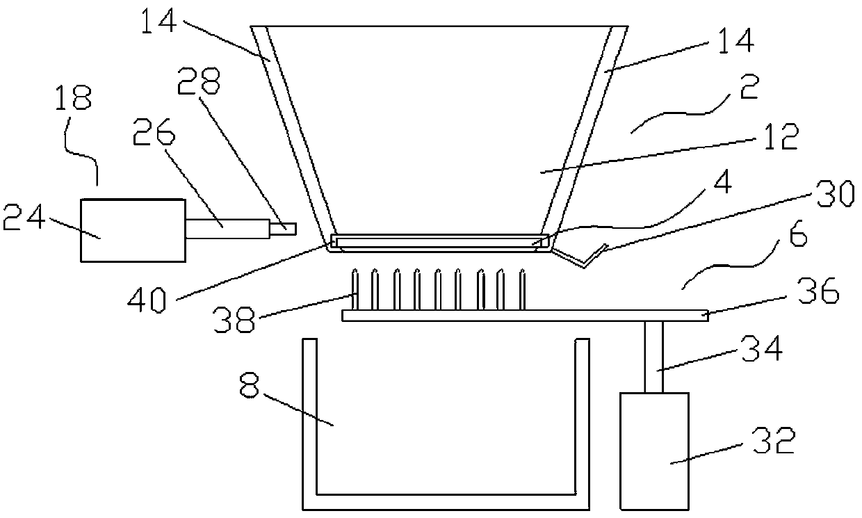
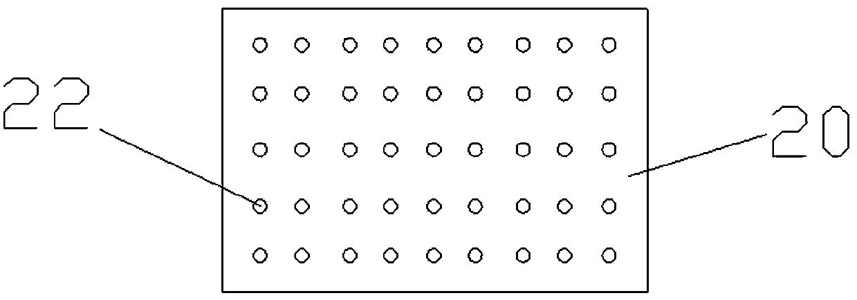
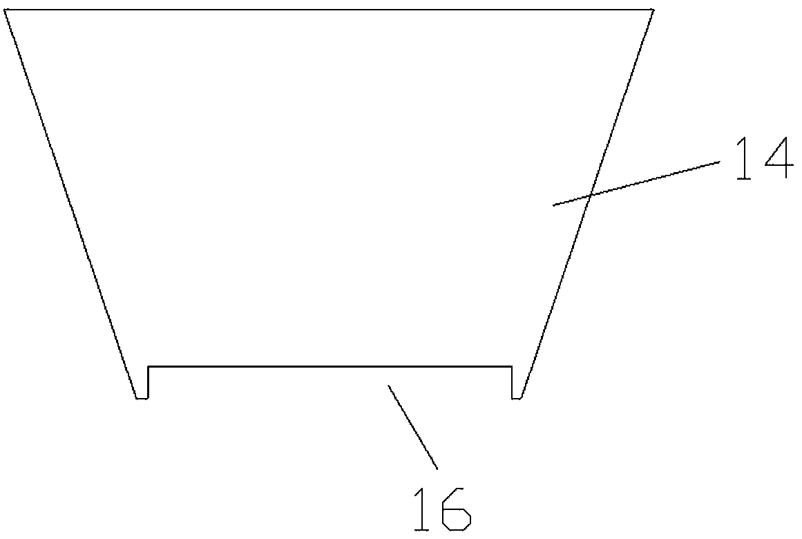
[0018] Such as Figure 1-Figure 3 As shown, a machine tool chip removal device includes a chip removal bucket 2, a filter screen 4 detachably installed at the bottom of the chip removal bucket 2, an insertion rod assembly 6 located below the filter screen 4, and a liquid storage device located below the insertion rod assembly 6 Groove 8, chip bucket 2 includes two oppositely arranged first inclined plates 12 and two oppositely arranged second inclined plates 14, the bottom ends of the two second inclined plates 14 are provided with notches 16, one of which is second A push-pull assembly 18 is provided on the outside of the inclined plate 14 ,...


PUM


Abstract

The invention relates to a machine-tool chip discharging device. The machine-tool chip discharging device comprises a chip discharging hopper, a filtering net, an insert rod component and a liquid storage tank, wherein the filtering net is detachably installed on the bottom end of the chip discharging hopper, the insert rod component is located below the filtering net, and the liquid storage tankis located below the insert rod component; the chip discharging hopper comprises two first inclined plates which are oppositely arranged and two second inclined plates which are oppositely arranged, the bottom ends of the two second inclined plates are both provided with gaps, and the outer side of one of the second inclined plates is provided with a push-and-pull component; and the filtering netcomprises a supporting plate and a plurality of through-holes which are arranged in the supporting plate. The machine-tool chip discharging device is simple in structure and convenient to use, a pushing plate passes through one of the gaps and pushes filtered waste chips on the filtering net out towards the other gap, the situation of the waste chips piling up on the filtering net is avoided, theblocking to the filtering net is avoided, a plurality of insert rods insert into the plurality of through-holes, the loosing of the waste chips inside the plurality of through-holes is realized, the waste chips are conveniently pushed out from the filtering net, a cutting-peeling liquid conveniently drops and falls into the liquid storage tank, the recycle of the cutting-peeling liquid is realized, and the cost is lowered.

Description

technical field [0001] The invention relates to machine tool processing equipment, in particular to a machine tool chip removal device. Background technique [0002] Because the machine tool is processing the workpiece, the mixture of high-speed chips and cutting fluid has a certain impact when it directly enters the chip removal device, making the sound particularly loud. At the same time, the cutting fluid will splash during the falling process, causing work The dirty environment not only causes waste of resources, but also affects the health of operators. Contents of the invention [0003] The invention overcomes the shortcomings of the prior art and provides a machine tool chip removal device with a simple structure. [0004] In order to achieve the above purpose, the technical solution adopted by the present invention is: a machine tool chip removal device, including a chip removal bucket, a filter screen detachably installed at the bottom of the chip removal bucket,...

Claims


Application Information

Patent Timeline
IPC IPC(8): B23Q11/00
CPCB23Q11/0042
Inventor 徐超
Owner SUZHOU BOLAIXI ELECTRICAL APPLIANCE CO LTD
Why Eureka
Try Eureka