Automobile part clamping device

An auto parts and clamping device technology, applied in the field of auto parts clamping, can solve the problems of inconvenience, easy clamping of auto parts, and inability to accurately monitor the clamping force, and achieve the effect of improving convenience and work efficiency

Inactive Publication Date: 2018-04-13
GUANGXI HONGXING MACHINERY CO LTD
View PDF0 Cites 6 Cited by
  • Summary
  • Abstract
  • Description
  • Claims
  • Application Information

AI Technical Summary

Problems solved by technology

[0002] Auto parts are the units that make up the whole car and the products that serve the car are collectively referred to as auto parts, which are classified as follows: engine parts engine, engine assembly throttle body cylinder block tensioner, drive train parts clutch Magnetic material for reducer, brake system accessories Brake master cylinder, brake wheel cylinder Brake assembly, brake pedal assembly Compressor brake disc, brake drum, steering system accessories kingpin steering gear steering knuckle ball head pin, travel It is the balance plate of the rear axle air suspension system, the sensor of the electrical instrument and other accessories. At present, in the inspection and maintenance of automobile parts, the parts need to be clamped, but the existing clamping device has a simple structure. The force cannot be accurately monitored, and the auto parts are easy to be clamped, which is very inconvenient. Therefore, we propose a clamping device for auto parts to solve the above problems

Method used


Image

  • Automobile part clamping device
  • Automobile part clamping device
  • Automobile part clamping device

Examples


Embodiment Construction

[0014] The following will clearly and completely describe the technical solutions in the embodiments of the present invention with reference to the accompanying drawings in the embodiments of the present invention. Obviously, the described embodiments are only some, not all, embodiments of the present invention. Based on the embodiments of the present invention, all other embodiments obtained by persons of ordinary skill in the art without making creative efforts belong to the protection scope of the present invention.

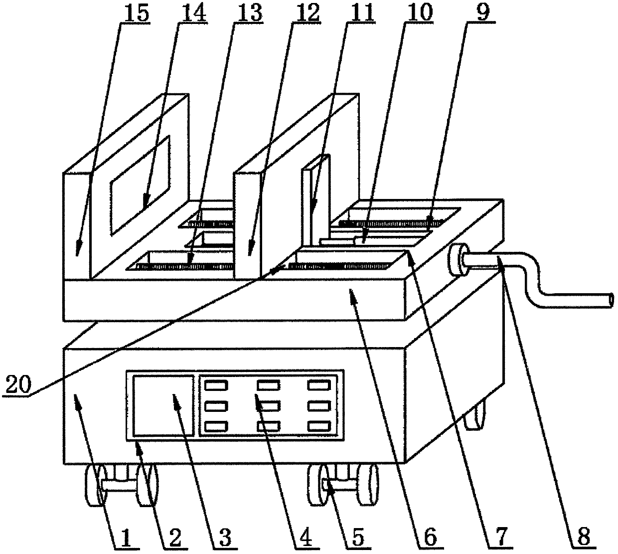
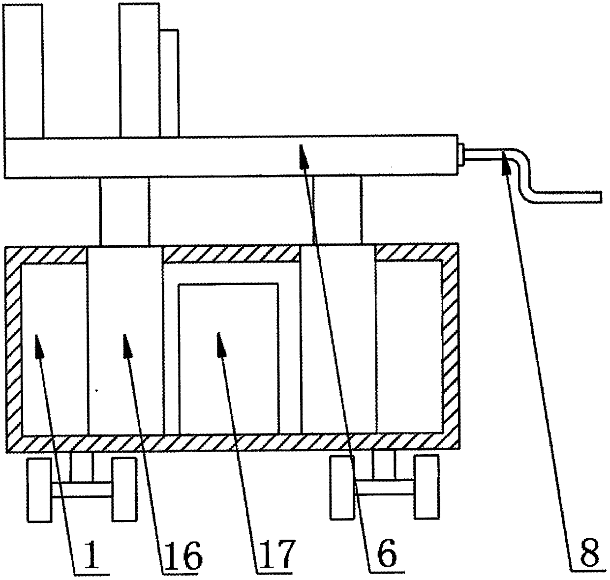
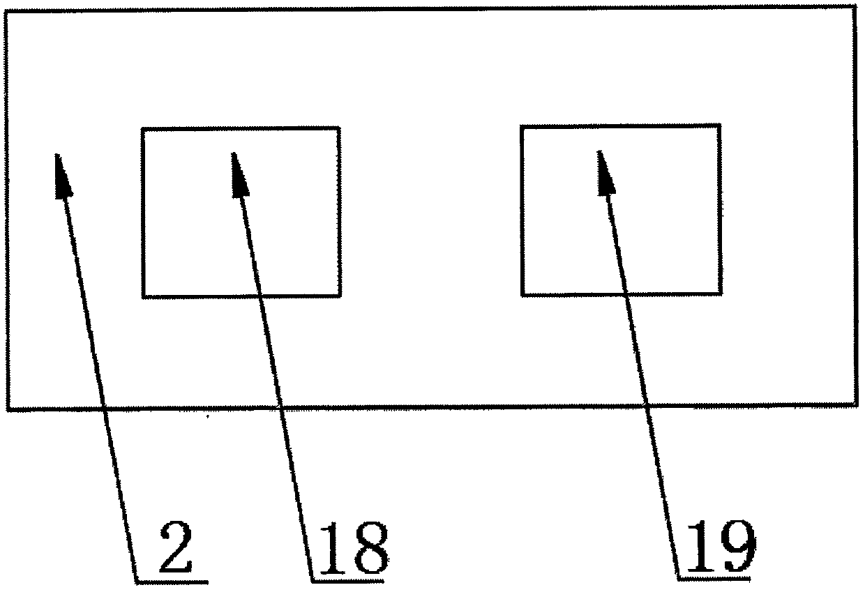
[0015] see Figure 1-3 , the present invention provides a technical solution: a clamping device for auto parts, including a base 1, an electric control box 2, a display screen 3, a control panel 4, a moving wheel 5, a bottom plate 6, a chute 7, a rocker 8, Limiting groove 9, first electric push rod 10, limit block 11, splint 12, screw rod 13, pressure sensor 14, fixed plate 15, second electric push rod 16, counterweight 17, alarm 18, PLC control device 19 and...


PUM


Abstract

The invention discloses a clamping device for auto parts, which comprises a base, an electric control box, a display screen, a control panel, a moving wheel, a bottom plate, a first electric push rod, a limit block, a splint, a screw rod, a pressure sensor, a fixed Plate, second electric push rod, counterweight, alarm, PLC controller and slider, the four corners of the bottom of the base are fixed with moving wheels by bolts, and an electric control box is embedded in one side of the base , one side of the electric control box is embedded with a display screen, one side of the display screen is fixed with a control panel by bolts, and the center of the bottom inner wall of the base is fixed with a counterweight by bolts, and the counterweight A second electric push rod is fixed on both sides by bolts, and the top of the second electric push rod passes through the top of the base and is fixed with a bottom plate by bolts, and a fixed plate is fixed on one side of the top of the bottom plate by welding. The device has a simple structure and is convenient to use, thereby effectively improving the convenience of use.

Description

technical field [0001] The invention relates to the technical field of auto parts clamping, in particular to an auto parts clamping device. Background technique [0002] Auto parts are the units that make up the whole car and the products that serve the car are collectively referred to as auto parts, which are classified as follows: engine parts engine, engine assembly throttle body cylinder block tensioner, drive train parts clutch Magnetic material for reducer, brake system accessories Brake master cylinder, brake wheel cylinder Brake assembly, brake pedal assembly Compressor brake disc, brake drum, steering system accessories kingpin steering gear steering knuckle ball head pin, travel It is the balance plate of the rear axle air suspension system, the sensor of the electrical instrument and other accessories. At present, in the inspection and maintenance of automobile parts, the parts need to be clamped, but the existing clamping device has a simple structure. The force...

Claims


Application Information

Patent Timeline
IPC IPC(8): B25B1/10
CPCB25B1/10
Inventor 杨毅坚杨湘潮
Owner GUANGXI HONGXING MACHINERY CO LTD
Why Eureka
Try Eureka