Biomass fuel drying device

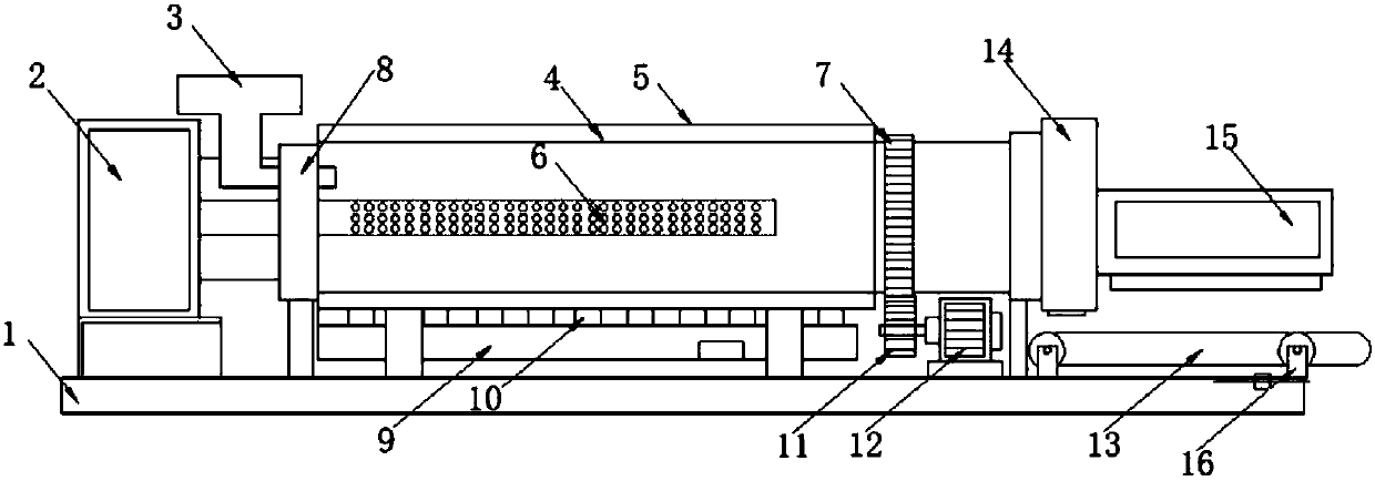
A biomass fuel and drying device technology, applied in biomass drying, drying, dryer and other directions, can solve the problems of inability to dry and pack biomass, inconvenient use of personnel, low production efficiency, etc., and achieve economical, practical and convenient. Fast, safe, reliable and stable use, and the effect of improving production efficiency

Inactive Publication Date: 2018-04-13
巴东隆生生物科技有限公司
View PDF0 Cites 1 Cited by
  • Summary
  • Abstract
  • Description
  • Claims
  • Application Information

AI Technical Summary

Problems solved by technology

[0002] Biomass fuel dryer is to dry the residual moisture in biomass, which has achieved the purpose of convenient transportation and storage. This drying equipment is suitable for wood chips, sawdust, bamboo chips, wood chips, shavings, barley straw, oats Drying of straw, wheat straw, rye straw, rice straw, sorghum straw, stalk and corn straw, potato vines and bean stalks, including soybean straw, broad bean straw, pea straw, cowpea straw, lupine straw and peanut vine, etc. For the drying of materials, for different biomass drying, because of its wide range of applications, it is widely used in real life. Traditional biomass drying equipment is mostly closed tank heating and drying, or drum type structure for drying, but there are problems of low drying efficiency and inconvenient use of personnel, and the traditional drying equipment has the problem of large dust when drying biomass, which affects the health of personnel and pollutes the environment. The traditional drying equipment needs to manually dry the biomass before bagging and packaging after drying the biomass. The production efficiency is low, and the biomass cannot be quickly dried and packaged efficiently and quickly, which affects the use and has shortcomings. , and the structure of traditional drying equipment is too complicated and inconvenient for personnel to use

Method used


Image

  • Biomass fuel drying device
  • Biomass fuel drying device
  • Biomass fuel drying device

Examples


Embodiment Construction

[0014] The technical solutions of the present invention will be clearly and completely described below in conjunction with the accompanying drawings. In the description of the present invention, it should be noted that the terms "center", "upper", "lower", "left", "right", "vertical", "horizontal", "inner", "outer" etc. The indicated orientation or positional relationship is based on the orientation or positional relationship shown in the drawings, and is only for the convenience of describing the present invention and simplifying the description, rather than indicating or implying that the referred device or element must have a specific orientation, or in a specific orientation. construction and operation, therefore, should not be construed as limiting the invention. In addition, the terms "first", "second", and "third" are used for descriptive purposes only, and should not be construed as indicating or implying relative importance.

[0015] In the description of the present...


PUM


Abstract

A biomass fuel drying device, including a base, one end of the base is fixedly connected with a hot air blower, the upper end and one side of the hot air blower are respectively provided with a feeding port and a drying pipe, and both the feeding port and the drying pipe extend through the shaft plate to the drying chamber Inside, the outer side of the drying box is covered with a dust collection chamber, and the lower end of the dust collection chamber is fixedly connected with a dust collection bag through a connecting pipe. The outer end of the drying chamber is located at the outer end of the dust collection chamber. . The beneficial effect is: through the design of the dust bag on the dust collection chamber and the through hole design on the drying chamber, the equipment can effectively solve the problem of large dust that is harmful to the health of personnel and the environment when drying biomass. , and through the design of the conveyor belt at the lower end of the collection port and the design of the cooling fan on the conveyor belt, it can be bagged after the biomass is dried and cooled by the cooling fan.

Description

technical field [0001] The invention relates to the field of biomass drying devices, in particular to a biomass fuel drying device. Background technique [0002] Biomass fuel dryer is to dry the residual moisture in biomass, which has achieved the purpose of convenient transportation and storage. This drying equipment is suitable for wood chips, sawdust, bamboo chips, wood chips, wood shavings, barley straw, oats Drying of straw, wheat straw, rye straw, rice straw, sorghum straw, stalk and corn straw, potato vines and bean stalks, including soybean straw, broad bean straw, pea straw, cowpea straw, lupine straw and peanut vine, etc. For the drying of materials, for different biomass drying, because of its wide range of applications, it is widely used in real life. Traditional biomass drying equipment is mostly closed tank heating and drying, or drum type structure for drying, but there are problems of low drying efficiency and inconvenient use of personnel, and the tradition...

Claims


Application Information

Patent Timeline
Patent Type & Authority Applications(China)
IPC IPC(8): F26B11/04F26B21/00F26B25/00F26B25/02
CPCF26B11/04F26B21/004F26B25/00F26B25/002F26B25/007F26B25/02F26B2200/02
Inventor 高红艳
Owner 巴东隆生生物科技有限公司
Why Eureka
Try Eureka